Categories
FAQ Uncategorized

Case good design – common error forgetting doors

Case Good Design – make sure to leave room on the front for frames and doors.

Next question from a user that might apply to more than this one person who was doing a case good design….

“If I want to add the doors at the end and forgot to leave front space for them I wasn’t able to move the whole assembly with exact 18 mm to the back to leave space for the doors without messing up the whole project – I had to start fresh again with the doors first.

I select assembly, input front 18, click on back for automatic calculation asks me for automatic resize and after it gives me error and dimensions come back to original. Moving with mouse is not exact and I get values with comas and is not that useful.”

I hate when I do this!  And I still do – after nearly ten years.  This very situation caused us to develop the batch move function.  In Adrian’s case he needed to push everything in an assembly back by 18mm.

Normally this means every value of ‘front’ in you case design needs to change from 0 to 18 and MOST of the corresponding ‘back’ values changed to move the board backward.  An exception happens when you need to shorten a board – like a side.  Then the front goes from 0 to 18 and the ‘width’ changes.

A few other precautions.

The project depth must be large enough to hold the new size of the cabinet.

The assembly depth must be changed to fit the newly located and sized boards.

BUT WAIT.  You are much better off using the Batch Move method.

  1.  Make the project depth big enough to hold the new depth of the assembly.  If may already be big enough but be sure to check.
  2. At project level – select the assembly you want to change and click the Batch Move button.
  3. Click – in this case – Front-Back
  4. Enter the move amount
  5. Chose Back or Front – pick accordingly.
  6. Exit

All set.

case design select assembly for batch move


case design room for door


Categories
Blog Uncategorized

Cabinet Design Software – clone function

Cabinet Design Software – using the clone functions to save time

 SketchList 3D cabinet design software  allows you to make exact copies of any object in your project by using the clone function. The clone function saves time by allowing you not to redesign the same part over and over again. (Somewhat related to this idea is the SketchList standard library where you can create an object design and save it for use in other places.) Imagine making a detailed cabinet with many shells, doors, and drawers and having to re-create that board by board each time. It’s much more efficient to simply select that assembly and clone it.

There are three types of clone within SketchList 3D.


  1. Clone – this makes an exact copy of the object highlighted.
  2. Clone and space – this makes any number of copies of the object. In addition it allows you to space the copies from bottom to top, left to right, or front to back.
  3. Clone and mirror – this allows you to make a copy of an object in mirror it 180° left or right.

There are different ways of initiating the clone command.

clone form

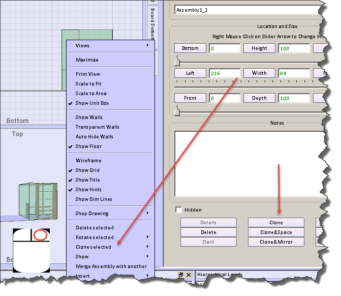
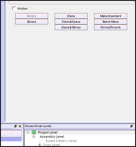
  • There is a clone button on the object form to the right of the SketchList 3D main screen
  • Right clicking the object opens a menu from which you can select the clone sub-menu. On that sub-menu you can pick any of the three clone techniques.
  • Right clicking a row in the spreadsheet will open a menu from which you can select the type of clone you desire.


clone sh

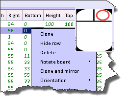
Cloning makes an exact copy of the original object. In the general spreadsheet you’ll notice the row is highlighted with the gold background. This means that an object has been cloned but not yet changed. This highlighting helps you see that there are indeed two objects in exactly the same space. When you change the name of the cloned object the gold highlighting will go away.

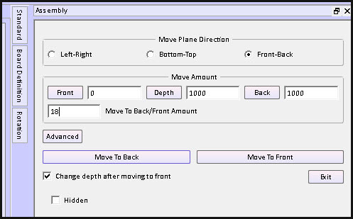
Usually the next step is to relocate the cloned object.

Clone and mirror makes a copy of the original object but inverts it left to right. If you had a bookshelf on the left of an assembly and drawers on the right cloning and mirroring would result in the second assembly where the drawers would be on the left and the bookshelf would be on the right.

Clone and space makes one or more copies of the original object. Objects may be clone and space in any of three directions – bottom to top, left to right, front to back.

form for clone and space

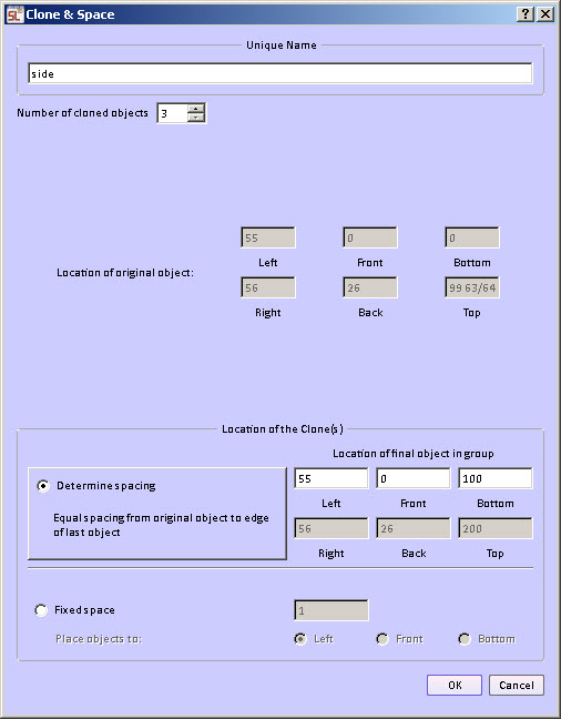
There are two different ways to do the spacing.

Fixed space between the cloned objects.  The space between, for example, the tops of shelves         and the bottom of the next shelf are equal for all pairs of shelves in the group. This way you can determine that the spacing between two objects would be a fixed amount, for example 10 units.

 Variable space between cloned objects. The space between the objects is calculated over a span you specify. The beginning of the span is the original location of the selected object. You enter the end of the span.   The ending of the span is set to the inside edge of the last object.   For example if a bookcase height is 100 units and the thickness of the shelf is one unit the ending span would be set to 99. The form provides a calculation to show the top, right, back edge of the last copy of the object.

In fact with the variable spacing option you can clone and space the boards in more than one direction. In the example below the boards were cloned and then spaced in all three directions. This provides a bit of a staircase functionality in SketchList 3D.

multi direction clone

Clone and space capability also exists within the round a non-round hole functions of SketchList 3D.  In that case you can select a hole and clone and space it.  [More later]

Watch the video.

Categories
Blog Uncategorized

Cabinet Design – grain, orientation, and materials

Cabinet Design Software – using board definition  tab to change grain, orientation and materials.

Creating a new board in SketchList 3D cabinet design software establishes a definition of that board that contains information about the orientation (what it looks like from the front of the assembly), grain direction, material type (for example sheet or dimension lumber), and material (species or appearance).

There are times when you may want to change some aspect of that definition.

To do that click on the board definition tab on the right side of the SketchList 3D cabinet design software main form.

 board defintion tab

 That opens the board definition form.  The current values for that board are already set in the form. If you want to change any just click an alternative value.

You may change any or all of four elements of the definition.

  1. Orientation – the way the board looks from the front of the assembly. This is really setting the board thickness so one SketchList 3D runs the Optimizer it knows how to lay this board onto the source material.
  2. Grain direction – the direction of the grain. The option any essentially means you don’t care.
  3. Material type – usually sheet goods or solid lumber, but there are other types of material such as glass, leather, or metal to name a few. There are also objects as a material type. In this category you may have stored an image of a refrigerator for example.
  4. Material – this is the name and the visual appearance (grain image) of the material you’re choosing for this board.


board definition form


When you’re finished adjusting that board definition move your cursor off of the new board form and it will close.

Watch the video.

Cabinet Design Software – using board definition tab to change grain, orientation and materials.

Creating a new board in SketchList 3D cabinet design software establishes a definition of that board that contains information about the orientation (what it looks like from the front of the assembly), grain direction, material type (for example sheet or dimension lumber), and material (species or appearance).

There are times when you may want to change some aspect of that definition.

To do that click on the board definition tab on the right side of the SketchList 3D main form.

board definition tab

That opens the board definition form. The current values for that board are already set in the form. If you want to change any just click an alternative value.

You may change any or all of four elements of the definition.

Orientation – the way the board looks from the front of the assembly. This is really setting the board thickness so one SketchList 3D runs the Optimizer it knows how to lay this board onto the source material.
Grain direction – the direction of the grain. The option any essentially means you don’t care.
Material type – usually sheet goods or solid lumber, but there are other types of material such as glass, leather, or metal to name a few. There are also objects as a material type. In this category you may have stored an image of a refrigerator for example.
Material – this is the name and the visual appearance (grain image) of the material you’re choosing for this board.

board definition form

When you’re finished adjusting that board definition move your cursor off of the new board form and it will close.

Watch the video.