Categories
Basics and How to

Cabinet Design Software – Learn Step by Step

Learning to design a cabinet using software, mystifies many people.  There are, at least,  two reasons for this.  Firstly some software is mystifying.  You have little control over this except not to use it.  Secondly it may be the approach you take in teaching yourself how to use the woodworking design software you chose to buy.   However the difficulties arise, you can do better if you break the process into smaller steps and slow down.  Therefore this series of posts and videos does just that.

Wooden cube 12 inches

Introduction

This article is the first of several that teach you to use SketchList 3D, our cabinet making software.  The ‘lesson’ begins by making a very simple wooden box.  A twelve inch cube with six surfaces.
Why a box?  It allows us to focus on basics.
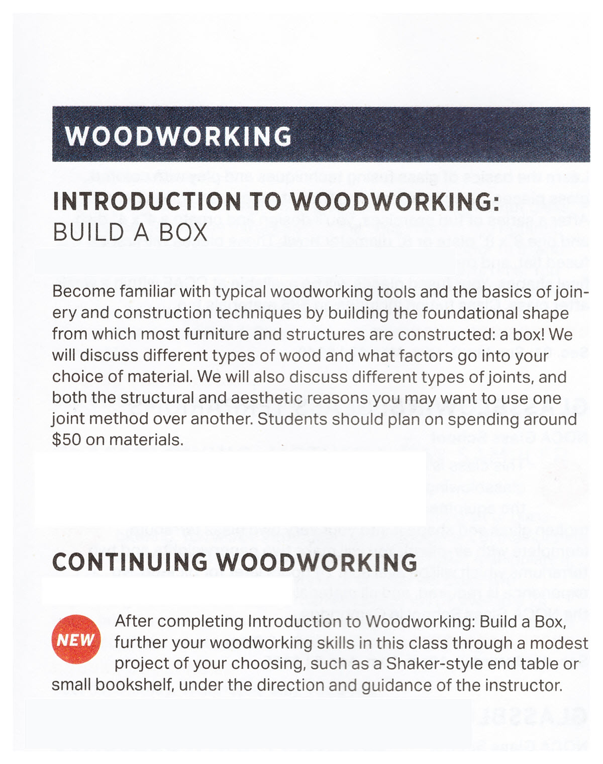
Which is funny since starting the post I picked up a copy of an adult education catalog.  And I usually do with these books I turned to the section of woodworking.  Then I saw it.  The first course is building a box!  Because with this you can start simple.  As a result you can focus on basics.  As a result if you do that well you’re building tools for your advancement.
Cabinet Design software image of wooden box

Actually the same if true in the real world [wood] and the virtual world [computer screens]. Please don’t dismiss the box building instructions in this post as too simple a project.  Do not skip over it or go too quickly.  If you carefully follow each step of this article and the video that goes with it you will learn in the shortest amount of time.

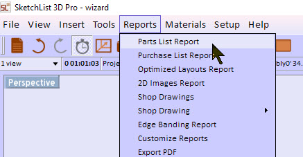
Topics covered in the video:

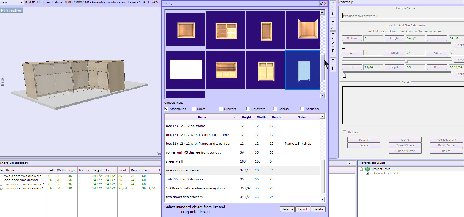
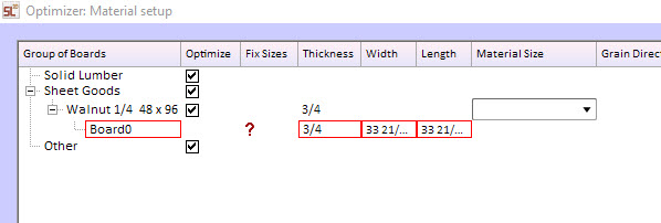
How assemblies work.
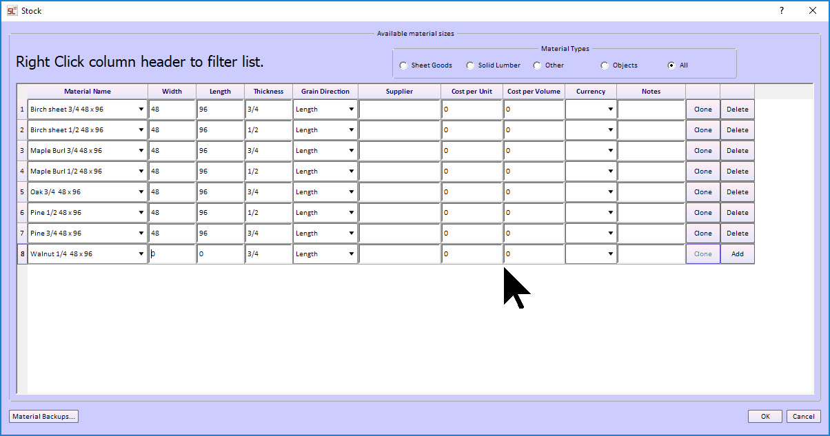
Adding boards to ‘build’ you project.  There are three board types in SketchList 3D woodworking design software.

  1. The vertical is for sides and dividers.
  2. The horizontal for shelving.
  3. The ‘flat’ is for backboards and such.

There are only three actions in SketchList  3D:  insert, resize, and locate.  First you insert a board into the assembly.  Certainly you must pick the correct type.  Then you size the board as needed.  And finally you locate that board.  You can think of it as if you are working in your shop.
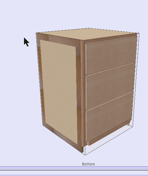
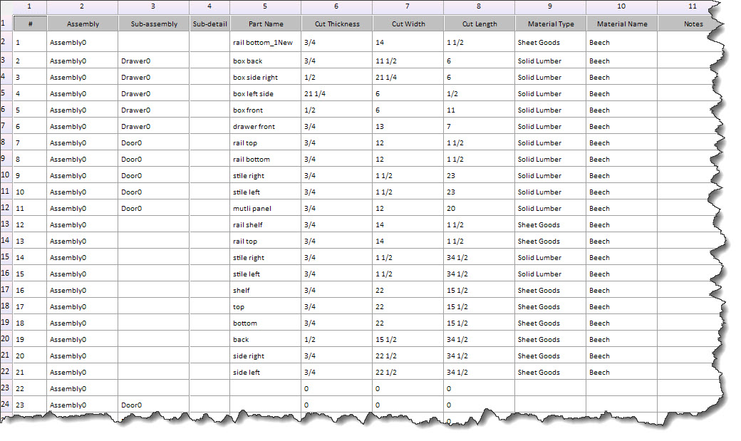
In our box there are two sides [vertical boards] top and bottom [horizontal boards] and front and back [flat boards].

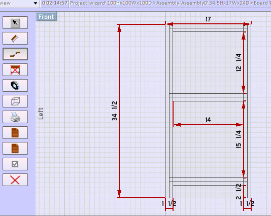
And only three tools accomplish the resizing and locating in cabinet design software.

  • First dots.  Red dots resize.  Blue dots locate.
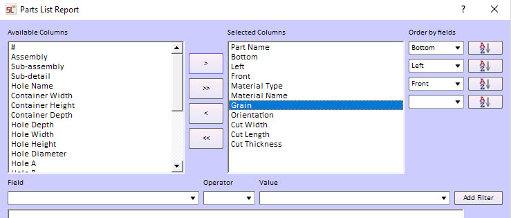
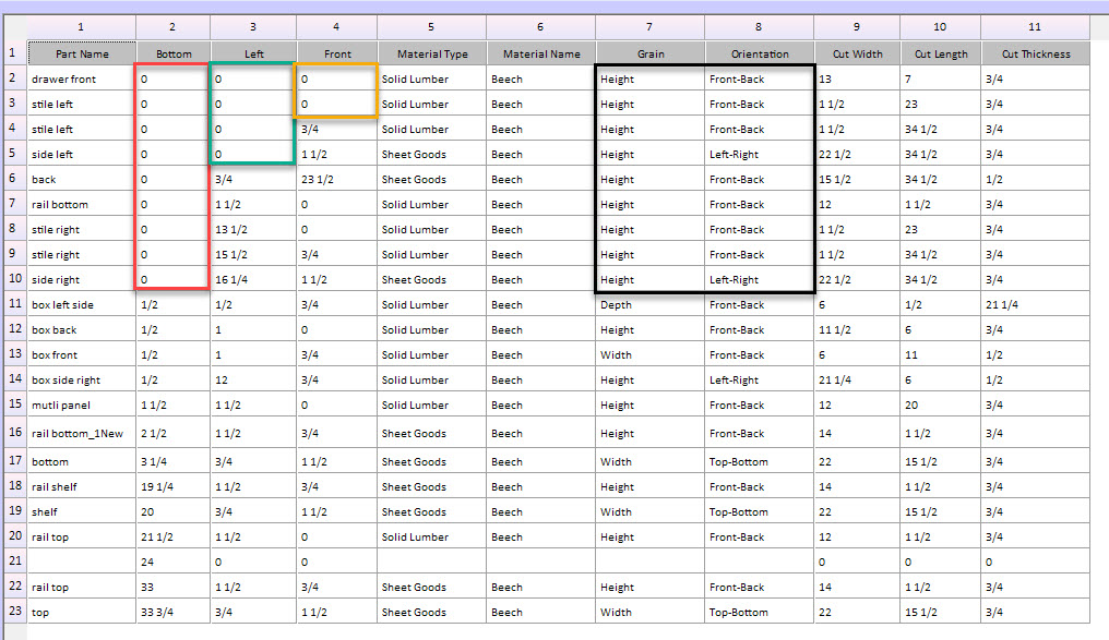
  • Next spreadsheet. Here you type in values for sizing and locating while seeing all the boards’ information is one display.
  • Finally form. With the form you focus on one board at a time, entering size and location information.

Remember, it seems simple but once you master them – you can design almost anything.

What is to come of our cube?

The box is finished.  After that the next video in the series we’ll add a face frame to the cube.  You’ll see slightly different uses of the tools.  For example there’s more use of the blue dot paste and copy [more on that next time!].  After that we’ll add a door and drawer.
Once we have that cube fitted out it will be used to demonstrate resizing, merging assemblies, rotating and locating for L shaped kitchens.
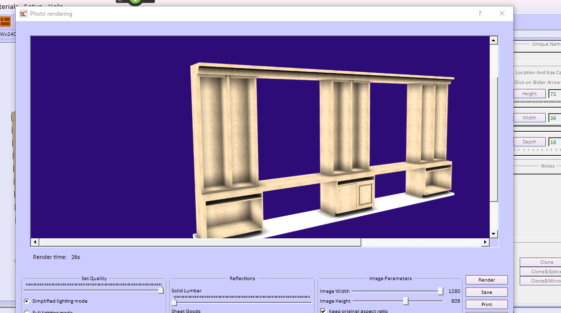
Certainly with all that progress we’ll venture off into making our little cube into a full blown entertainment center.

Categories
Basics and How to

Edge Banding in Cabinet Design Software Projects

Edge banding as addressed by SketchList 3D.

Edge banding is a material applied to cover the rough edges of plywood to improve appearance.  Plywood and melamine-coated particleboard have plenty of advantages over solid stock, but you do need to cover their edges.

Overview

Edge banding is a thin, pre-sanded veneer tape.  Made of wood or other material it is glued onto the edge of plywood. Its purpose is to give the appearance of a solid piece of wood.   The veneer banding tape used has a heat-sensitive glue coat and applies quickly with an iron.  Applying a veneer results in a clean and solid-wood look.
Edge banding comes in most species: birch, oak and cherry.  Search online for more exotic species.  Rolls of banding come in lengths of 8 ft. to 250 ft. and various widths.  For 3/4-inch thick plywood people generally use either 13/16- or 7/8-in.-wide banding.
In higher volume shops an edge banding machine applies the decorative veneer to one or more sides of the boards.  The complex machines apply the edge banding, press it onto the wood, and cut it accurately and neatly.
SketchList 3D Pro treats edge banding as a type of contour.  To the extent the banding changes the appearance of the edging that category fits.  Honestly it is such a standalone, not frequently used function it doesn’t justify it’s own category of menu item!
How to apply edge banding to boards.

Follow these steps.

  1. Select a board and go to the board detail level. Double click the board or click the Board Detail level in the hierarchical level form.
  2. Click on an edge on which to apply the veneer. It will turn green in color.
  3. Click the button Contour.
  4. Select Edge banding.

Set up the way you want to apply the edge banding.
steps to edge banding

After clicking the button Band Edging:

  1. Enter the thickness of the material.
  2. Click on one or more edges to receive the material.
  3. Select the material texture.

edge banding parts list

Notice that the cut sizes of the part is reduced by the thickness of the banding material.  For our example purposes the thickness is two inches.  The result is that the length and width of the board is 4 inches less than the nominal or design size.  Four inches comes from two inches on each side or edge.

Edge Banding Report.

SketchList 3D accumulates the total footage of the banding material necessary for all the boards with banding material applied.  To see that report click the reports menu item and select the report.
edge banding report menu

Notice that in our project the sample boards contain two different band thicknesses.
Edge banding report

The banding shows up on the boards in the 3D view of SketchList so you can easily identify which boards contain the banding.
edge banding in 3D image

Edge banding machines span a wide range of features and prices.  Here is an example of a edge banding application machine. LINK

rockler edge bander

Of course, machines with many more features and capabilities are available at a wide range of prices.
See more on using contours in SketchList 3D by following this link.

Categories
Basics and How to

Room cabinet design using the SketchList 3D library

Room cabinet design using the SketchList 3D library speeds designs.

Recently we did a survey of SketchList 3D users.  Users were asked what the liked about SketchList 3D and what needs improvement.  The ‘needing improvement suggestions’ included good ideas that we’ll try to include in Version 5, suggestions we don’t understand, and those we already do but obviously need further explanation.  One response fell into – sort of – the room cabinet design category.
Here it is.

“More YouTube videos showing us how to set up the program, add pre-existing cabinets together to the kitchen design without having to put us through making each box! It should just be a snap and not hours of stress.”  This comment is related to the need for room cabinet design.  Certainly to save time.

Adding pre-existing cabinets – This post will deal with the question “How can I quickly put together a set of cabinets?”

That question takes me back to the very beginning of SketchList 3D.
Room cabinet design
I needed to design a breakfront or display cabinet.  I used that opportunity to search out some cabinet drawing software to help make a better design.  Well good luck!  In my opinion my choices were either cabinet design programs that were expensive and only allowed work on a cabinet basis or CAD programs that only allowed me to work on a line by line basis.  And SketchList 3D was born!  I thought we needed a middle ground between boxes and lines.  So Sketchlist 3D uses 3D boards.  Because of that you can design at a more detailed level than a cabinet with less detail than lines, rectangles and squares.
Of course, there is a cost to that.  You must design what you want to build.  While that seems always to make sense to me – some people don’t want to take the time to make their own designs.  I get it.  Remember – because you are creating your own design it conforms to the way you work in your shop.  That’s the custom part of custom woodworking.
The other part of it certainly for the professional or business user – is speed.
So the challenge is combining customer approach with an Ikea type of pick cabinets from a list to do your room cabinet design.

Remember Sketchlist 3D supports a library function that allows you to create and  store for further use a wide variety of standard objects.

These include:

  1. Boards
  2. Doors
  3. Drawers
  4. Assemblies
  5. Hardware
Categories
Basics and How to Case Studies

Furniture design program- adding doors.

 Furniture design program provides flexibility to modify designs.

Once the concept of the project has been developed and approved we moved on to providing the details. 
There were several areas that had to be finished off before the cut list, shop drawings, and sheet goods lay out reports could be generated.  This post and the video included will demonstrate several aspects of detailing the project in our free furniture design software.

We’ll make a list of these details.

1.       The most obvious that doors need to be created, size and located as needed in the design.
2.       Each lower base unit will have a drawer added.
3.       The upper cabinets that merged to 18 inch wide cabinets into one 36 inch wide cabinet needs work.

  • Merging the two cabinets just cloned and “stuck” them together.  Because of this the right boards from one cabinet and the left boards from the other cabinet repeat. Go into the cabinet at the assembly level and delete one of those redundant board pairs.
  • The center dividing board (vertical) along with its stile must be centered it in the cabinet
  • All horizontal boards must be examined to make sure they butt against the two side boards and fit under the center divider.
  • This new merged cabinet will be cloned and moved, replacing the other merged cabinets.

Making adjustments to the merged cabinets best shows how to use the red dot in the line tool in our furniture design program.

furniture design software
F
ollow these steps.

  • First select the cabinet and click assembly level in the hierarchical level form.
  • Then click on one center style and delete it.
  • Click on that Stiles vertical divider and delete that.
  • Click on the backboard and with your mouse drag the right board to the left edge of the right side of the cabinet drag the right side of the cabinet.  Check that the right side edge of the backboard is equal to the left side edge of the right side.  (This is where the video will help.)
  • Now click the backboard and holding down the shift key on your keyboard click the divider board.  In the upper right area of the sketch list main screen click the alignment button and click the icon at the left top.  That will center the style in the cabinet
  • Repeat that step centering the divider board.
  • For the top and bottom of the cabinet, the boards to the right of the cabinet. The SketchList 3D cabinet making software allows you to use a red dot method of shift drag [hold down the shift key and drag a red dot] to change the size of the top and bottom boards.  This way they fit between the left and right-side boards.
  • Final check is to make sure that the center divider sits on top of the bottom board and underneath the top board.  

At this point will put in the door using our furniture design program

  1. Drag the door icon into the assembly.
  2. Using the form at the top right enter a depth of three quarters and click the button back.
  3. Click the bottom shelf and noticed that the top value is 3 and three quarters. 
  4. Click and using the form change its value for bottom from 0 to 3 ¾.  Then click the button labeled top.
  5. Change the left value of the door from zero to ¾.  
  6. Change the top value for the door to 20.25.   This is the bottom value of that middle shelf.  Click the button labeled top.
  7. Finally change the right side of the drawer to the value of the left edge of the right side board.  In the case of this example it’s 35 ¼. 
  8. Realizing that that is a very wide board were going to go into the with text box in the form and multiply that value by .5   I’ll show you how to do that in the video showing the use of my furniture design program.  The resulting new width of the door is 17 5/8. 

Break time!  The container for the door is all set.  Now we insert the needed boards.

  1. At this point go  to the door level and insert the boards necessary to build your door.   Simply drag the board icon from the top of the sketch list screen into the door.  You can use the red dots to change the size of the board so that it completely occupies the door container.   That would be for a flat panel door.   To create a raised panel or five-part door you would adjust the sizes needed to make the board into the Stiles. Then you would locate one style on each side of the door.  Really the clone and mirror button works very well here.
  2. Insert another board for the lower rail. Use red dots, form, or spreadsheet to size that rail.  Remember you can use the red dot while holding down the shift key method to drag and snap the rail to fit between the styles.
  3. Clone the lower rail and use the slider bar to move it to the top of the door.
  4. Drag in one more board for the center panel.   It’s easiest to use the shift key red dot drag method to place the center panel between the rails and the styles.
  5. Finishing the left door, click on the clone and space button.  At the bottom of the form check fixed space and enter the value of zero. Make sure the left direction is selected and click okay. (For the purposes of this demonstration I’ve ignored door and drawer overlay or inset values.)

Perhaps this is a lot of information to consume in written format.  For that reason I’m including this video showing all the above using our furniture design program – SketchList 3D.

Categories
Basics and How to

Cutting list for kitchen cabinets – materials

Cutting list for kitchen cabinets begins with material creation.   If your kitchen design software doesn’t have information about the materials you want to cut, how will it know how to cut it?  That seems simple enough.
Over the past week or so several people called in with questions about our cabinet cut list report.  Mostly the questions arise after the design is completed and running the cut list report [diagrams] shows errors.  SketchList 3D users know these as red boxes around part names in the report.
Hint make sure you read this post to the end!

1.       The size of the material is not in the stock database.
2.       Selecting the wrong board orientation for a given board.
3.       Specifying an incorrect grain direction for a board.
#1  Size missing.  Simple to see in your cutting list for kitchen cabinets.  If the pull-down menu to the right of the part list is blank the size is missing.

cut list optimizer no size
 
Solution – click the open stock button at the bottom of the screen.

This form opens and you can enter the sizes of the material.
#2 Wrong orientation.  You picked the wrong icon for the board.  Any strange thickness, like 23” and not ¾” is a big hint you picked incorrectly.  Best solution?  Delete and redo board.  Really.
3 board icons
#3. Incorrect grain direction on board.  In the optimizer click the ‘Select part in design” and look at the board.  Does it look right? 
Solution.   Select the board, click the board definitions tab, and change grain direction.

In working on these users questions I developed a scheme that makes both designing and reporting easier in SketchList 3D.  That deals with handling the materials.

First – material name.  I include the material size right in the name.  Not just Pine but Pine ¾ x 48 x 96.  This better shows the size material you want along with the parts name.
Second – be careful that you pick the correct type of material, either sheet goods or solid lumber.
Third – This is good!  At the start of a project click Materials menu item and select materials.  Find the material you WILL use in this project and double click on it.  Then edit the name by adding the @ symbol at the front of the name.  Now when you sort the material lists by clicking the column header, the ones with @ at the front pop to the top of the list.  And generally, they stay there.  I find most SketchList users employ a small number of materials over all the projects they do.   In this case walnut is on the top of the list and not the bottom.
optimizer material list
 You can reduce the height of the rows to see more materials in the window.   Clicking the check mark will keep the window open.  To close it click the check mark again.  If you click the X you will need to go to View – tabs to see the material tab again.
optimizer material list
Notice in this example shows three thicknesses for my birch plywood.  This saves time and reduces mistakes because I see the thickness I want on the list.  (NOTE – user hint.  If you use 2 x 4 and 2 x 6 boards – create both in your materials database.  Or else the optimizer might want to cut the 2 by from the 6 by stock.)

Hopefully you will find these hints useful as you generate your Cutting list for kitchen cabinet.


Categories
Basics and How to

A cutlist is for more than cutting wood!

A Cutlist is more than a list of parts – or should be.

Most of the people considering using SketchList 3D want a cutlist report for their work.  In Sketchlist 3D, a cutlist  provides a series of functions that help you go to the shop and turn the cut list into parts.  This post will show you several ways to use a cut list report most effectively.

The first version of a cut list is found under the reports menu item in Sketchlist 3D. 


cutlist report menu items
his is the simplest version of the cutlist.

The cut list contains the:

  1. ·         assembly name
  2. ·         part name,
  3. ·         cut thickness,
  4. ·         cut with,
  5. ·         cut length,
  6. ·         material,
  7. ·         material name,
  8. ·         and notes.

 As you can see from this sample report, all the information you need to cut and produce your project is available in SketchList 3D.  Any changes to your design, additions, deletions, or resizes, are automatically  updated in this report.

parts list cut list

 But how to make it more useful?     Use the Parts List report.

 To get to the report click Reports – Parts List Report.

parts list report menu

 This opens a very powerful form that allows you to specify exactly which information appears on the report, sort that in three levels, and filter information by value.

parts list specificationFor example, select part name, material type, and dimensions.  Then sort by material type and part name, then display only parts with a thickness = 1.

But there is more.  You can add the location information for each part – left, bottom, and front – and sort on it. 

 With that sort order you get information about the assembly.  You see which boards are at the front, bottom, left of the assembly.  [Note that the values are relative to the board’s container.  So a left of zero for a door stile means zero in the door container.]

 To check on it, I threw in the grain direction and board orientation.  If for example your side board had its thickness going from bottom to top – well that is the wrong orientation for a side board.

parts list sorted

This listing provides a good quick check on the project.  Throw in a shop drawing and you are even better prepared to start cutting.

parts list shop drawing

 Even if you use SketchList 3D Pro and generate optimized cutting layout diagrams, this approach to cut list reports will help you check, organize, and assemble you project. 

To read something a bit more general about cutlists, see this post.