Categories
Basics and How to Furniture Design Software SketchList 3D – Guides Woodworking Business

Parametric Design vs CAD – Woodworkers Beware the Difference

Parametric Design vs CAD:  In the world of design, particularly in fields such as woodworking, architecture, and manufacturing, the tools and techniques you choose can significantly affect the outcome of your projects. While the terms drawing, CAD, and 3D modeling may sometimes be used interchangeably, they each have distinct characteristics and applications that can serve different needs. Let’s dive into the differences and see how each method can benefit your design process.


 Drawing (2D)


image of wall unit


  • Drawing is the traditional method of creating flat representations of objects by hand with paper and pencil or digitally using software like AutoCAD in 2D mode.
  • It provides a clear view of an object through flat views such as top, front, and side elevations. Think of it as the foundational step in visualizing your ideas.
  • One of the most significant drawbacks of traditional 2D drawing is the lack of depth or volume, making it challenging to visualize complex designs.
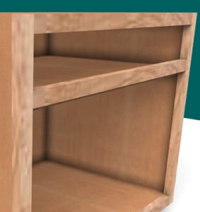
  • Picture a blueprint for a cabinet, clearly showing the height, width, and depth dimensions but without a view of how those elements come together in three-dimensional space.


person looking at screen


CAD (Computer Aided Design)

  •  2D CAD (like AutoCAD 2D): This functions more like a digital drawing with tools for enhanced precision.
  •  3D CAD (like SolidWorks and Fusion 360): This brings depth into the mix but often involves complex workflows that might require a steeper learning curve.
  • Presents a digital way to create precise technical drawings or 3D models.
  • It’s widely used in engineering and architectural designs, integrating measurements, materials, and technical specifications into the plans.
  • Traditional CAD programs can be quite complex and sometimes demand solid technical knowledge, which can be challenging for beginners.
  • Think of a CAD plan of a kitchen cabinet, complete with cut lists and detailed joinery specifications. This can be exceptionally helpful in ensuring accuracy before you even start working with your materials.


Screen showing SketchList design with keyboard for cabinet design software

 3D Modeling

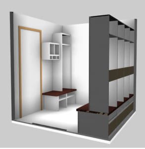
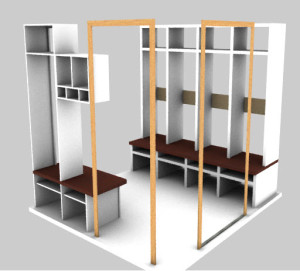
As the name suggests, 3D modeling focuses on creating three-dimensional representations of objects that can be visualized from any angle.

  • Primarily aimed at enhancing visualization, prototyping, and realistic representation of designs.
  •  More straightforward to visualize compared to 2D CAD.
  •  Ability to simulate materials, textures, and lighting realistically.
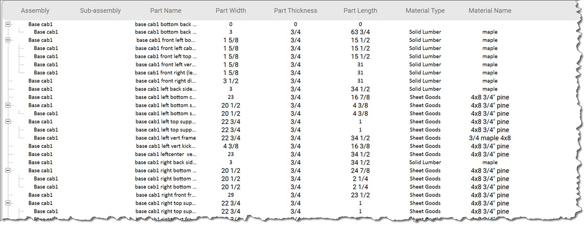
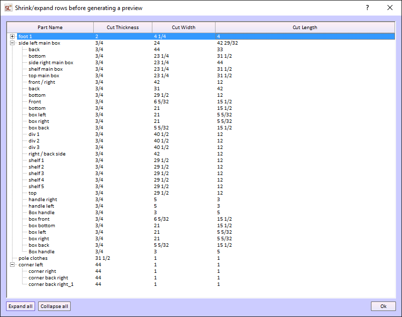
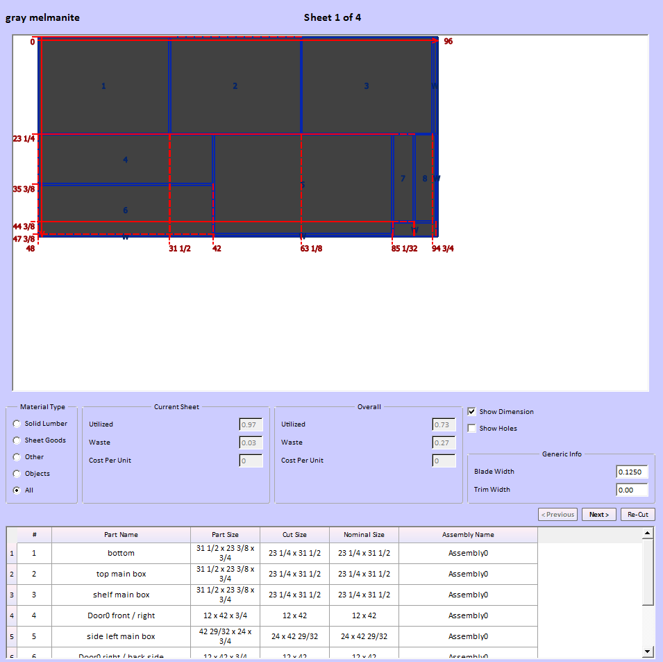
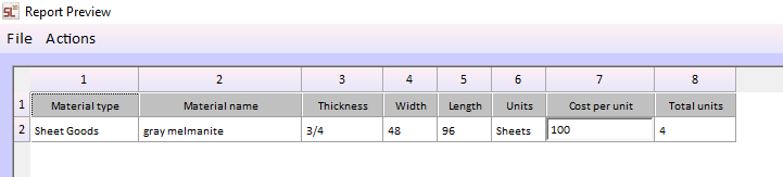
  •  Some software can generate reports automatically, such as cut lists and material layouts.


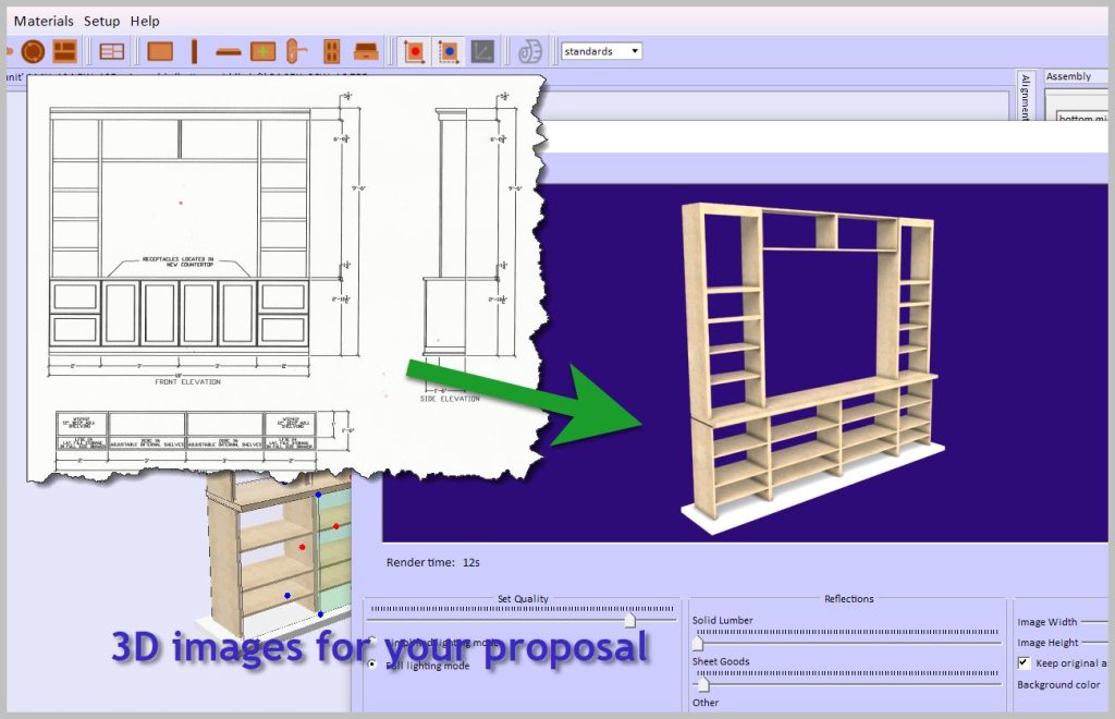
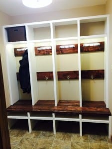
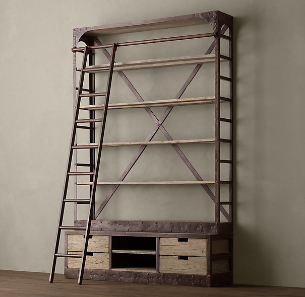
Example: Picture a 3D cabinet model that allows you to rotate, zoom, and see how each part fits together. This will give you a complete understanding of your project before making cuts.

woodworking software image of cabinet


 Summary of Differences


Feature

Drawing (2D)

CAD 3D Modeling
Dimension 2D 2D & 3D Fully 3D
Ease of Use Easy Can be complex Easier than CAD for visualization
Visualization Flat views Some 3D features Fully interactive models
Best for Simple plans layouts Engineering, technical design Concept design, woodworking, furniture making

Parametric Design vs. CAD Drawing: Which is Best for Woodworking?

Choosing the right software in woodworking design can mean the difference between efficiency and frustration. Traditional CAD drawing and parametric design are two common approaches, but they serve different purposes. Parametric Design vs. CAD is a key distinction. If you’re a woodworker looking to streamline your workflow and improve accuracy, understanding these methods’ differences is essential.

What is CAD Drawing?

CAD (Computer-Aided Design) drawing is a digital version of manual drafting, allowing designers to create 2D or 3D representations of objects. While CAD is widely used across industries, its approach is still largely manual and static.

How CAD Works

  • Objects are drawn using lines, arcs, and shapes.
  • Dimensions are manually assigned to different components.
  • Each change to a drawing often requires manual adjustments to related parts.

Limitations of CAD for Woodworking

  • Time-consuming edits: Adjusting one part does not automatically update others.
  • Lack of relationships: Objects contain no information about what they are, do, or are made from.
  • Manual resizing: If you modify a design, all dependent components must be adjusted separately.

For example, if you design a cabinet in AutoCAD, resizing it means you have to manually adjust shelves, doors, and supports, which can lead to extra work and potential errors.

What is Parametric Design?

Parametric design takes a different approach by defining objects using rules, parameters, and relationships instead of just shapes and lines. This means components are linked, so changes in one part automatically update the others.

How Parametric Design Works

  • Uses constraints (e.g., “this board is always 3 inches thick”).
  • Components have built-in relationships, so modifying one element affects the entire design.
  • The software calculates and adjusts all related dimensions instantly.

Key Benefits of Parametric Design for Woodworkers

  • Faster modifications: No need to manually adjust each part when making changes.
  • Consistency and accuracy: Ensures all components stay correctly sized and aligned.
  • Less repetitive work: Once parameters are set, modifications require minimal effort.

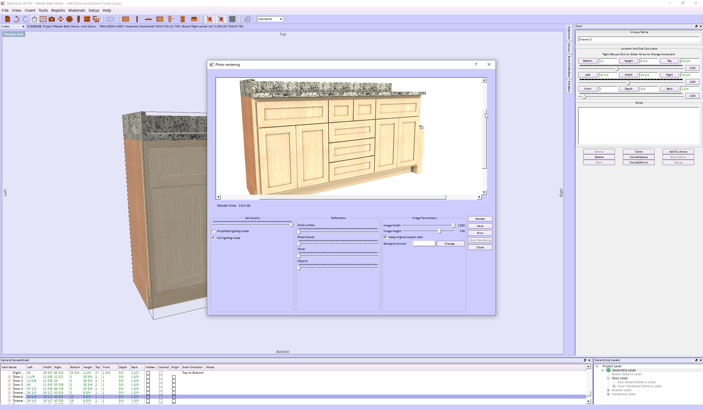
For example, in SketchList 3D, if you increase the width of a cabinet, all connected parts—doors, shelves, and supports—automatically adjust to fit. This eliminates tedious recalculations and ensures design accuracy.

CAD vs. Parametric Modeling: Which One is Better?

Feature CAD Drawing Parametric Design
Editing Manual adjustments required Automatic updates based on rules
Relationships No built-in relationships Components adapt to changes
Flexibility Limited, time-consuming edits Highly flexible and dynamic
Error Reduction Prone to inconsistencies Ensures consistency
Best for Basic layouts, technical drawings Complex, adaptable designs

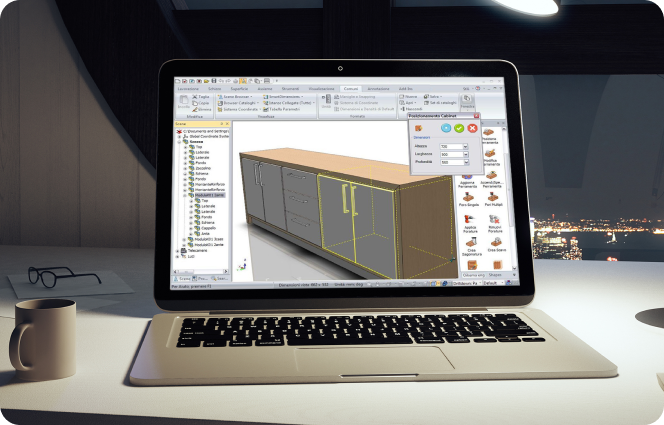
Why SketchList 3D is a Game-Changer for Woodworkers

SketchList 3D is designed specifically for woodworking, combining the best of parametric modeling with an easy-to-use interface. Unlike traditional CAD programs, which can be complex and time-consuming, SketchList 3D allows you to:

  • Quickly modify designs without redoing entire drawings.
  • Automatically generate cut lists and reports as you design.
  • Visualize projects in realistic 3D, making client presentations easier.

If you’re tired of struggling with manual CAD adjustments, parametric design with SketchList 3D can save you time, reduce material waste, and help you create more accurate designs.

Final Thoughts on Parametric Design for Woodworking

While CAD drawing has its place, parametric design offers a far more efficient solution for woodworkers who need flexibility and precision. If you want to spend less time fixing design errors and more time building, a parametric modeling tool like SketchList 3D is the way to go.

If you are wondering where SketchUp falls in this discussion, read this.

For more information, see this.

Ready to upgrade your workflow? Try SketchList 3D and experience the benefits of parametric design for yourself!  See why many call it the best software for woodworking.


Categories
Contractor Woodworking Business

Woodworking CAD Software – Reports are #1


woodworking cad software report


The world of woodworking has embraced technology with open arms. Computer-aided design (CAD) stands out in this tech-savvy workshop. It transforms ideas into tangible realities. For woodworkers, CAD isn’t just a tool; it’s a game-changer, especially when managing production. CAD reports are crucial in ensuring that each project is executed with precision.

What Are Woodworking CAD Reports?

Woodworking CAD Software reports are detailed documents generated from your CAD designs. They aren’t just blueprints; they provide insights into every aspect of a woodworking project. These reports contain dimensions, materials, and the step-by-step assembly process. They offer a comprehensive guide that ensures the project aligns with the original vision.

Types of CAD Reports in SketchList 3D

  1. Material Lists: These reports list all materials needed for the project, ensuring nothing is left out.
  2. Cutting Diagrams: Visual guides showing how each piece interacts with the others, minimizing waste during cutting.
  3. Cut Lists:  Report the lists of every project part by type and species, including sizes.
  4. Shop Drawings:  Fully dimensioned shop drawings.

Benefits of Using CAD Reports in Woodworking

Integrating CAD reports into woodworking design has many benefits. Whether you’re designing a simple chair or a complex cabinet, CAD reports are indispensable.

Enhanced Accuracy and Precision

Before CAD, measuring twice and cutting once was the mantra. With SketchList 3D reports, accuracy is now in-built. By relying on precise data from detailed reports, woodworkers can avoid errors. The precision offered by woodworking CAD software can be a significant advantage. Learn more about how CAD offers precision and visualization in woodworking.

Streamlined Workflow

Efficiency is synonymous with woodworking CAD reports. From planning to execution, every stage benefits from calculated insights. These reports help map out a project’s journey, reducing the likelihood of mid-project halts.

Best Practices for Creating Woodworking CAD Software Reports

Creating a CAD report requires careful planning and execution. Here are some best practices to keep in mind:

  • Choosing the Right Software
  • Not all CAD tools are created equal. Some woodworking CAD software excels in 3D modeling, while others shine in 2D drafting. Software like SketchList 3D is popular among woodworkers for its simplicity and efficiency. For beginners, SketchList 3D offers an intuitive interface.
  • Integrating Feedback and Revisions
  • Woodworking is a craft, and no two projects are the same. Incorporating feedback into your reports is essential for improvement. Revisions help tailor the project to specific needs and rectify potential issues early on. Design and reporting must integrate with design,  as in SketchList 3D. Every design change is automatically reflected in all the reports. If not, changes in the drawings may not make it to the cutlist, and it is out of sync with the design. This is not good.

Conclusion: The Future of Woodworking CAD Software Reports

The future of woodworking lies in seamless integration with technology. CAD reports have shifted from being optional to essential in modern woodworking. They represent a blend of tradition and innovation, ensuring craftsmanship never loses its touch. Accordingly, as technology evolves, these reports will undoubtedly become even more integral, with precision and creativity. Now, consider whether you ever imagined that tech would profoundly shape craftsmanship.

Categories
Blog Uncategorized Woodworking Business

Woodworking design application helps avoid losing job bids.

 Challenges Facing Your Cabinet-Making Business


woodworking design application


Losing Business Due to Poor and Delayed Proposals

The impact of a poorly crafted or late proposal can be daunting. First impressions matter deeply, and it’s heartbreaking to think that a single slip could tarnish your reputation. A disorganized submission might lead clients to question the quality of your work. It’s understandable to feel concerned about the long-term effects this could have on your ability to attract new business. Creating clear proposals can help rebuild confidence and enhance your credibility within the industry.


Timeliness in Proposal Development


We know the pressure of promptly delivering proposals can weigh heavily on your shoulders. In a fast-paced market, you need more time to prepare a proposal to avoid losing clients. Those seeking personalized cabinetry often juggle tight schedules, and understandably, your delays can create an impression of disinterest in the job. It’s important to remember that timely responses can reflect your respect for clients’ needs and showcase your dedication to their projects. Streamlining your proposal-making process can be a huge relief, helping you stay competitive without the added stress.


Developing Proposals without quality images is a terrible business.


It can be disheartening when you put in so much effort only to find that your proposals lack high-quality images. It’s natural to want your work to shine; without stunning visuals, your true talent may be overlooked. This can feel frustrating, especially when you know the quality of your craftsmanship deserves recognition.


Redfin investigated the value of professional-looking images.  They found that people viewed offerings with great images 60% more than those without. Furthermore, 47% of offerings with good images sold faster and at higher prices.  


Investing in imaging capabilities is about more than looks; it’s about fostering trust and showing clients the professionalism they seek.


Difficulty in Making Design Changes


It’s not uncommon to struggle with making last-minute adjustments to the plans, especially at the job site, where client preferences can shift suddenly. Clients expect flexibility, and it is tough when you cannot accommodate their evolving visions. You have a lot of work to do in the shop and with other prospects.


Embracing tools that allow quick revisions can enhance your adaptability and strengthen your relationship with clients, showing them that you will meet their needs.


Lack of Essential Reports for Building Projects


cabinet design software rendered


We recognize the importance of having thorough reports for your building projects. Without detailed specifications and accurate measurements, the risk of missteps increases significantly, which can lead to costly errors down the line. This pressure can be incredibly stressful, especially when these complications affect timelines and budgets. Prioritizing comprehensive design software alleviates much of this pressure, helping ensure your operations run smoothly and efficiently.


Consequences of Not Addressing These Issues

Ignoring these challenges can lead to feelings of frustration and concern. We all want to provide the best service possible, but we must focus on these areas to ensure customer satisfaction and retention. In a market where reputation is everything, it’s heartbreaking to think that discontented clients could tarnish your hard-earned image. Operational inefficiencies and errors can also lead to financial strain, making it harder to sustain your passion for your craft.


Taking Action: Use a Woodworking Design Application.


Introducing SketchList 3D, a comprehensive woodworking design software that addresses the critical challenges cabinet-makers face. It automatically creates high-quality images, produces a complete set of reports for planning and purchasing, creates cut lists and shop drawings, and optimizes sheet good layouts. Most importantly, any change in design instantly updates all the outputs, saving you time and effort.

SketchList’s woodworking design application provides:

  • A catalog of existing projects.
  • A library of cabinet objects.
  • A Cabinet Wizard that creates cabinet designs in minutes.


SketchList 3D is designed to replicate the experience of working in your shop, using the same terms, techniques, and ideas you’re familiar with. You can create designs by organizing virtual boards on your screen, adding a joint with a few mouse clicks, and making changes quickly and easily. The intuitive and user-friendly software ensures a smooth transition for your business.  


We understand that facing these challenges can be tricky, but taking action now can lead to a brighter future for your business. With SketchList 3D, you’re not alone in this journey. By addressing these concerns thoughtfully, you can create a positive path forward, feeling reassured and confident in the relief and peace of mind that the software can bring.


By using Skechlist 3D, you’ll get better-looking proposals in less time. The software’s checks while designing lessen the chance of making an error. Changes take a small fraction of the original version’s time. The reports are integrated and instant and help communicate with workers and customers.


Don’t just take our word for it. Here’s what some of our users have to say about the SketchList 3D woodworking design application:


“I got new orders thanks to my craftsmanship and SketchList 3D! They told me they couldn’t believe how fast I produced their new kitchen concept drawings.”


Lou Farkas


“I’ve had Sketchlist for a few weeks now and already sold four jobs with it. I just figured out how to put all four wardrobes into one project and run the optimizer to see what materials to order! Thanks, you just saved me some time!”


Shawn Jensen


“The trial version was very helpful in one of my larger jobs, and the finished product was spot-on for the on-site installation. The client LOVED the piece, and we’re discussing another large job.”


Robert Hsu


How do you get to success in implementing a woodworking design application?


We will work with you. That means, in part, we provide you with videos, tutorials, and free online training meetings; we are also available via email, text, or phone to help you. With SketchList 3D, you’re not just getting software; you’re getting a team dedicated to your success, making you feel supported and cared for in your journey to enhance your business operations.


Now, forget those frustrating and disappointing times when you find out your proposal was not accepted. And the time invested and the money from the job is lost.  

With the SketchList woodworking design application, you save time and have all the designs and input you need to win jobs. Winning a job brings great satisfaction in terms of the money earned and how a satisfied client can make you feel about your skills and professionalism. This sense of accomplishment and satisfaction can be a great source of motivation and inspiration for your work.

Check here for pricing.


Categories
Blog Contractor Training Version 4 Woodworking Business

Furniture design software – 2 dimensions?

Furniture design software – easier in two dimensions?

furniture design software 2D

I am reading a book on dimensioned shop drawings and drafting practices for woodworkers using furniture design software.  A survey we did showed us that users place a very high value on shop drawings.

The book starts with an explanation of drawing by hand, transitions to using computer programs to generate two dimensional drawings, and then moves to how to create full three-dimensional images.

The author says  you began your 3D design effort by drawing a front side and top view in two dimensions and blend them together to create your  three-dimensional design. I’ve not done that so I don’t know if that’s right or not.

I have read articles and online comments and commentary that say that  two-dimensional design is simpler than three. Makes sense and I think I agree.

Then I thought since drawing in two dimensions is easier than drawing in three dimensions it might help new users of SketchList 3D understand the process if I put together a video creating a model using the two dimensional method.

In the video you’ll see that I use the side, top and front views to create a bookcase.

If you are a novice to SketchList 3D this video will help you understand some of the tools and processes  one goes through to create a three dimensional design using two dimension representations.

But the best thing to do is watch the video.


Categories
Blog Contractor Training Version 4 Woodworking Business

Complete solution case design software

coashes box 2

A manufacturer wanted to see how SketchList 3D would work as case design software.

There is plenty of detail here, a review of all reports, and a good example of the kinds of information you get from SketchList 3D.  It applies to manufacturing, cabinet making, remodeling — anywhere you need to model, manage and produce your work.

The first step is to determine your output requirements, the first of which are the images.


coachs box with drawer liners

The door would have a hinge allowing it to close against the back part of the box.  The two drawers would also ‘close’.  There is a round metal bar for hanging clothing and a set of heavy rubber casters on the bottom.

coaches case wheels

A large part of the quality of the image has to do with images available for use [like the handles], angle or view of objects, background color and light adjustments.

box handle

One report available in SketchList 3D is PDF output.  This exports the design to a file that Adobe PDF reader [free software available from Adobe] can open or your or your client’s computer and actually move the design around on the screen.

In addition to being able to examine all views of the design, the
users can change lighting, make a line drawing, and modify their view of it.  SketchList 3D users tell me they love this feature.  Remember they can rotate it with their mouse.

The PDF can give different looks.  And it’s free.

coaches box pdf outline

Other types of outputs include the following:


  1. Shop drawings – this example shows a standard drawing. You can make as many drawings, as detailed as needed, as you want.

coaches box drawing


  1. Parts List – any part of the design can be shown or not on the parts list. The list can be sorted many different ways.  You can specify – for example – only parts of a certain thickness to be shown on a reports list.  The parts list can be exported to a spreadsheet for more work – for example inventories.  Of course you can print it.

coaches box parts list

  1. Optimize material layout diagrams. SketchList 3D will take all parts and lay them out on the specified materials in a way the reduces waste.coaches box itemized
  2. Purchase report.SketchList 3D takes the material requirements from the layout function, aggregates them, and produces a report showing how much of each type of material is needed and what that costs.  This example from the travel box is very simple.coaches purchase report
  1. Export to DXF files for use by your CAM software is generated from the layout function.

Consideration of the objects of each output is important.  Certainly drawings and reports go to the shop.  They will also be part of proposals to potential customers, input for estimating and quoting jobs, and web page and marketing materials.  Each use of output starts with the same information and perhaps presents it a bit differently.

The other desired output is a library of standard designs, components, and parts.  The travel box design incorporates wheels, handles, and corner material which can be saved as standards.

One early task in implementing SketchList 3D might be to create a list of the contents of the library.  Of course this can be done as you go along, but experience shows this can result in multiple parts which are really the same with different names.

Once a library of “boxes” is created, new projects can be a matter of taking an existing ‘box’ and changing its size.  This may be the entire process or you may make other types of modifications – such as adding drawers.

The output will definitely adjust as you gain experience with the software and the process.

Planning the setup steps is important.

Again this can be done as you progress, but some thought should occur front end.

When you start you will put some effort into determining the elements of your design.

  1. Joinery types – what kinds of joinery do you use and where?
  2. Materials – standard materials for all jobs and/or custom material for custom jobs?
  3. Materials cost – entering what you pay for the materials and vendors.
  4. Report contents – what data will be on the reports.
  5. Customer setup – entering customer information and including it on report headers.

Thinking about design structures. 

The effective use of assemblies and sub-assemblies greatly enhances productivity.  This is a skill you will develop as you become more experienced with SketchList 3D.  For example, in the travel box I used one assembly and included in it a large door.  That might have been two assemblies – there are advantages to each approach.

Starting

There are several steps.  Once you purchase SketchList 3D you can begin training and setup.  We do remote training via the internet and telephone,

Many customers find they become very productive with only two training sessions.  In the first we cover basics and begin to design a project they are about to begin.  At the end of that session probably 80% of the work is finished.  The user will attempt to finish the other 20% on his or her own.  During this time, I answer questions via email, phone, of sometimes with an online computer connection.  The second session covers final questions, resolves problems or misunderstandings, and reviews report generation.

The two session approach works because in the case of a customer woodworker – there is really not that much complexity.  They know how they build, build more or less the same thing over and over, and usually do not use the entire set of features of SketchList 3D [at least at first].

Your situation may be like that or may be more complex.  The more detailed cutting of foam inserts, more complicated case interiors, different use of materials all can affect the time to learn and adjust.

SketchList 3D will provide you an easy to learn and use design tool that will enable you to create both custom and standard parts and products.  Your customers will love the images they will see before buying.  It is certainly easier to get sign off when you have a detailed picture of what they are paying for.

Creating a standard library of objects will help you quickly and accurately create new designs.

The parts list, purchase list, cutting diagram, shop drawings, and DXF files will help you manage your production.

Categories
Blog Contractor Uncategorized Version 4 Version 4 Video Woodworking Business

Cabinet design software inserting shelf pin holes.

V4_hole_space

This is an introduction to holes and hole cloning in SketchList 3D cabinet design software.

This is a very useful feature if you are using shelf pins in your cabinetry. The basic process is to take a board and insert a hole at your first location.

When the hole is set up the way you want exit the form.  Next click on the edit holes button.  When the hole spreadsheet opens right-click on the row containing information about the hole you want to clone.  Pick clone and space from the menu list that opens.

Enter the number of holes you want to insert and the space between the holes.  Select if you want to clone horizontally or vertically.  You will see that SketchList 3D equally spaces those holes on the center line of the holes.   Exit the form.

At this point you might clone the existing holes but sometimes it is just easier to create another new hole for second line of shelf pin holes.

This basically involves repeating the process described above.

When finished do a ‘clone and mirror’ to make a mirror image copy with the shelf pin holes on the inside surface of the board.

Categories
Blog Contractor Uncategorized Version 4 Version 4 Video Woodworking Business

Not Only Cabinet Design Software – Design Almost Anything

Realistic Images in cabinet design software

Not limited to cabinet design software.  How Would You Like a TV, Painting,  or Fireplace..in your design?

Since I published the blog post showing and telling about William LaRue’s  built-in bookcases I’ve gotten several e-mails asking:  “Well how did he do that”?  First answer – he’s real smart.  Second answer – smart enough to buy SketchList 3D.

Well today I put together a video to show you at least in part how he did that.   His proposal to his client was very detail and very complex. The attached video shows how I took an image of a television and imported that image into SketchList 3D as a new material.

Then I took that material and set  its size  to 30 inches wide by 20 inches tall both in the horizontal and vertical scale section of the new material dialogue, and in the material size window.

Inserting a board into an assembly I picked the material called  TV for that board.  Using the flat orientation with the grain direction running top to bottom I size that board to be 20 inches tall and 30 inches deep.

You can see the result of the board in the image the top of this blog post.  The next steps had to do with putting on a black material as sides and back onto the television.

It’s really not that difficult and if you tried a few times you will get it.  When I first started this I had some of the grain directions incorrect and maybe the scaling factors were off a bit.  As I learned and adjusted it became almost trivial to create these objects.
It seems that you can do just about anything that has flat surface.   In fact for the stove that I have in my appliance library I used an image of the front of the stove for the front, and I took an image of a top of the stove with the burners and use that as the top of the stove.   Sandwiched between two base cabinets it looks very realistic.  So I guess like the headline says – SketchList 3D is really more than cabinet building software.  But of course it does that very well also.

When I get a bit more time I’m going to experiment taking some photos of objects with a green background.   My editing software allows me to then drop that green off so the image will stay with no background. I’m thinking of something like a trophy that you might put on the mantle or a mantle clock.

As we start planning for version 5 of SketchList 3D  it may very well be that we can have the ability to import real CAD files and create real 3-D objects in your cabinet design software.  The development jury is still debating that one.

Send me an e-mail and let me know how it goes.   Anyone else up for pasting a blog / story about SketchList 3D?


Categories
Blog Contractor Uncategorized Version 4 Woodworking Business

Cabinet Design Software Enables Face Frame Placement

Face Frame on Case

How to place face frames on your case work.

Had an good online training session Saturday morning with a few SketchList 3D users.  Covered placing objects and moved onto joinery – dado placement on board surfaces.   One user wrote in that it helped him along and still had a question on face frames.

So here is a video on using the cabinet making software for putting frames onto your case work.  It is basically a matter of placing – in this case – five boards on the front.  Remember the ‘back’ value of the frame must equal the ‘front’ value of the case boards!  In addition you use the FLAT orientation for frames – since you are looking at the assembly from the front and want to see the rail or stile surface and not its edge.  Grain direction – usually – is width for rails and height for stiles.  Match up the various lefts and rights, tops and bottom and you will be all set.

What I forgot!  Of course you can contour the corners of the frames and / or miter them as well.  They are just like any other board in SketchList 3D.

Categories
Blog Uncategorized Version 4 Woodworking Business

Cabinet Design Software Helps User Design Projects

lockers design 2

Email sharing a story of how cabinet design software aids work…

Got this email with some very nice photos of work that Pieter Minnaar did in SketchList 3D AND in the shop – of course.

He wrote:

“I recently used your V3 software very successfully in creating built in Lockers for our mudroom. I will include photos of the design and how it turned out at the bottom of the e -mail.

lockers design 1

finished lockersphoto 2 of lockers

I’m very impressed with the software and when the opportunity came by to get the Pro version of the new V4 I grabbed it and bought your V4.  I now have a new project–> building three Bookcases (shelving) I will include a photo of the inspiration to my new design.

A big part of these shelves will be angle Iron.  Unfortunately I’m really struggling to design this hardware (angle Iron).  Can you please help me with this? I did try your vid but didn’t quite get it right.
The angle Iron needs to be 1 1/2″ by 1 1/2″ and of variable lengths.
 proposed shelving
Thanx in advance for your help.”
It’s interesting because this is the second time in about a week that I’m doing a project with angle iron parts.
I did a quick video to show how to do this.
Just as I uploaded this to You Tube I realized I didn’t show how to re-size it.   You go into the hardware level and just enter new values for height or top.  You can also, I think, stretch or shrink at an assembly level.  Think about it a bit – you’ll get it right.  also rotate the hardware is very useful also but that is in the video.
The photos follow.