Categories
Contractor Woodworking Business

Woodworking CAD Software – Reports are #1


woodworking cad software report


The world of woodworking has embraced technology with open arms. Computer-aided design (CAD) stands out in this tech-savvy workshop. It transforms ideas into tangible realities. For woodworkers, CAD isn’t just a tool; it’s a game-changer, especially when managing production. CAD reports are crucial in ensuring that each project is executed with precision.

What Are Woodworking CAD Reports?

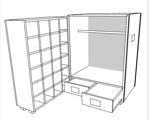
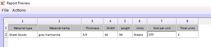
Woodworking CAD Software reports are detailed documents generated from your CAD designs. They aren’t just blueprints; they provide insights into every aspect of a woodworking project. These reports contain dimensions, materials, and the step-by-step assembly process. They offer a comprehensive guide that ensures the project aligns with the original vision.

Types of CAD Reports in SketchList 3D

  1. Material Lists: These reports list all materials needed for the project, ensuring nothing is left out.
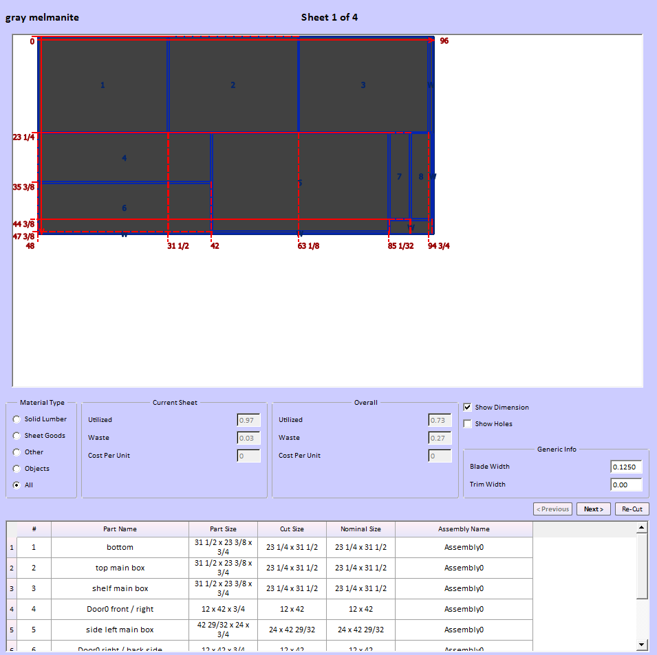
  2. Cutting Diagrams: Visual guides showing how each piece interacts with the others, minimizing waste during cutting.
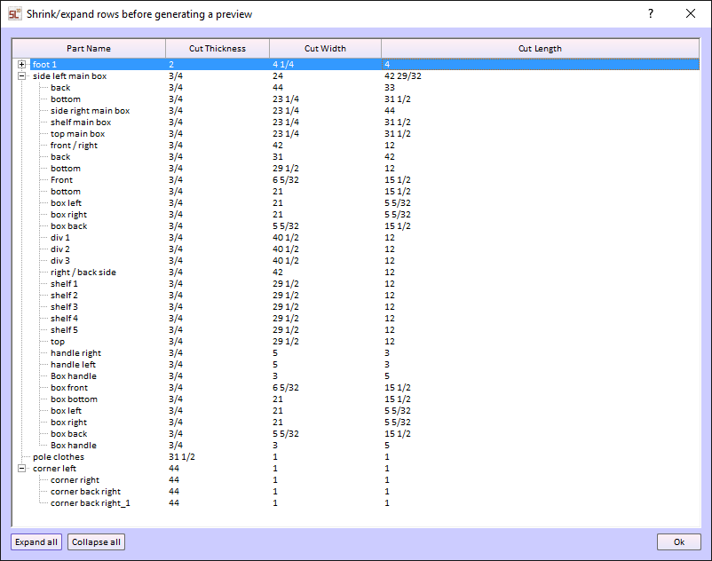
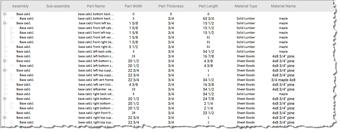
  3. Cut Lists:  Report the lists of every project part by type and species, including sizes.
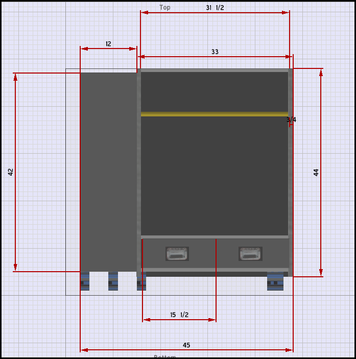
  4. Shop Drawings:  Fully dimensioned shop drawings.

Benefits of Using CAD Reports in Woodworking

Integrating CAD reports into woodworking design has many benefits. Whether you’re designing a simple chair or a complex cabinet, CAD reports are indispensable.

Enhanced Accuracy and Precision

Before CAD, measuring twice and cutting once was the mantra. With SketchList 3D reports, accuracy is now in-built. By relying on precise data from detailed reports, woodworkers can avoid errors. The precision offered by woodworking CAD software can be a significant advantage. Learn more about how CAD offers precision and visualization in woodworking.

Streamlined Workflow

Efficiency is synonymous with woodworking CAD reports. From planning to execution, every stage benefits from calculated insights. These reports help map out a project’s journey, reducing the likelihood of mid-project halts.

Best Practices for Creating Woodworking CAD Software Reports

Creating a CAD report requires careful planning and execution. Here are some best practices to keep in mind:

  • Choosing the Right Software
  • Not all CAD tools are created equal. Some woodworking CAD software excels in 3D modeling, while others shine in 2D drafting. Software like SketchList 3D is popular among woodworkers for its simplicity and efficiency. For beginners, SketchList 3D offers an intuitive interface.
  • Integrating Feedback and Revisions
  • Woodworking is a craft, and no two projects are the same. Incorporating feedback into your reports is essential for improvement. Revisions help tailor the project to specific needs and rectify potential issues early on. Design and reporting must integrate with design,  as in SketchList 3D. Every design change is automatically reflected in all the reports. If not, changes in the drawings may not make it to the cutlist, and it is out of sync with the design. This is not good.

Conclusion: The Future of Woodworking CAD Software Reports

The future of woodworking lies in seamless integration with technology. CAD reports have shifted from being optional to essential in modern woodworking. They represent a blend of tradition and innovation, ensuring craftsmanship never loses its touch. Accordingly, as technology evolves, these reports will undoubtedly become even more integral, with precision and creativity. Now, consider whether you ever imagined that tech would profoundly shape craftsmanship.

Categories
Campaign: More Effective Shop Contractor

Design Furniture Like a Pro: The Benefits of Using Cabinet Building Software

Design Furniture Like a Pro: The Benefits of Using Cabinet Software for Cut Lists

Shed Design

A professional furniture builder is faced with the exciting challenge of crafting a custom cabinet. But with an endless list of choices, what design should they go with? Cabinet software for cut lists is the answer.

There are many advantages to using design software compared to manual drawing methods. The world of cabinet and home design is more accessible now than ever. There are tons of programs and apps available that allow you to bring your ideas to life.

Cabinet software for cut lists has revolutionized the way that professionals build and design furniture. It allows you to design custom cabinets quickly and easily, saving precious time and money. It also helps professionals communicate better with customers and keep track of their orders.

You don’t have to have years of experience in tech to learn how to create realistic renderings. Tools are more intuitive than ever. All you need is a little patience and a willingness to try new things.

If you’re looking to learn more about cabinet software for cut lists, keep reading to find out what they can do for you.

Increase Precision and Accuracy

Cabinet software for cut lists can help you create your designs faster, with precision and accuracy. The software guides the user through the whole process with step-by-step instructions. With its help, complicated designs that would normally take hours or even days to finish can now be completed in minutes.

Using cabinet software for cut lists also helps you get the exact measurements you need for the furniture. This means that furniture pieces will fit perfectly, without having to worry about them being too big or too small for the room. It also helps eliminate the need for countless trips to the hardware store looking for supplies.

With cabinet software for cut lists, you can figure out all the measurements and materials you need in just a few clicks. With its help, you can design and build amazing pieces of furniture for your clients. It’s an invaluable tool that all furniture designers should have in their arsenal.

Better Visualizations

Furniture design software helps users visualize their design by providing a digital mock-up of the project. This allows you to make alterations and view the design layout before making it in a physical form.

Not only does the software make furniture design easier, but it also gives users an improved visualization of the structure as a whole. Other benefits of the software are customizing it to fit measurements, viewing it from different angles, and adjusting lighting sources at any time.

As you work on your project, features such as “walk-through” and “fly-over” make the visualization come to life. With the ability to make design modifications on the spot, our software makes furniture design a breeze.

Save Time and Improve Productivity

Cabinet software for cut lists helps to save time and improve productivity. It makes it easier to create stunning cabinetry pieces with a few simple steps.

When using this software, you can adjust the placement and size of cabinets, along with details like countertops, shelves, and drawers. You can even generate a 3D rendering to get a better understanding of how the space will look before you start building it. This software does all of the difficult work is done for you, allowing you to focus on the finishing touches.

Some of these software programs come with calculators and other tools that will help you figure out the exact measurements for optimal efficiency. Cabinet software for cut lists is a great tool for any furniture maker, as it helps to automate the design process and saves time so that you can produce more beautiful pieces faster.

Producing Photo-Like 3D Images

Designing furniture can be a difficult and tedious process, especially when you are starting out. Many inexperienced designers rely on guesswork and luck when it comes to putting pieces together. However, there’s a better way to go about designing custom furniture.

Woodworking design software is an effective tool for creating professional-grade pieces. This software can help you accurately lay out furniture pieces according to specifications.

Producing photo-like 3D images with woodworking design software gives buyers an up-close view of their product before it’s manufactured. With the software, it’s easy to make changes and adjustments, rather than starting over from scratch.

Create Optimized Material Layouts and Total Cost

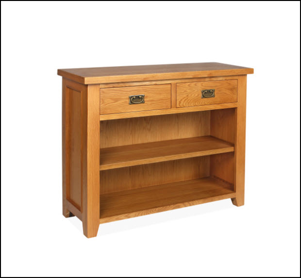
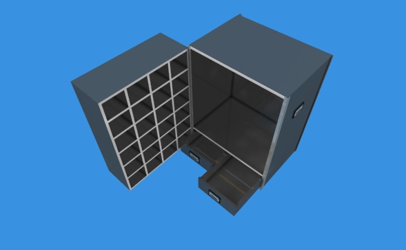
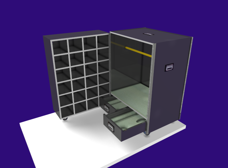
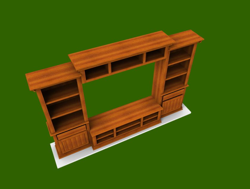
Furniture designers and woodworkers can use the software’s visual 3D design interface to transform their raw ideas into fully-functioning cabinets and furniture. It has a variety of features that help simplify even the most complex design projects with ease.

With its built-in tools for estimating material lists and generating cost quotes, the software allows furniture designers to create budgets and manage material lists with speed and accuracy. It also provides an automated way to visualize parts and assemblies so that designers can create optimized material layouts, resulting in cost savings and improved productivity.

Try Our Cabinet Software for Cut Lists Today

Cabinet software for cut lists not only simplifies the entire production process but also improves functionality, productivity, and accuracy. It also helps you cut down on costs and reduces production waste.

This software simplifies how furniture designers come up with ideas, make specific layouts, and bring designs to life. You can digitize workflows, ensure accurate measuring, optimize materials, and create automated schedules. Cabinet software for cut lists remains an effective instrument for both tailored and mass production.

If you’re looking for new cabinet software for cut lists, we’re here to help. Contact us today with your questions and to learn more.


Categories
Blog Contractor Training Version 4 Woodworking Business

Furniture design software – 2 dimensions?

Furniture design software – easier in two dimensions?

furniture design software 2D

I am reading a book on dimensioned shop drawings and drafting practices for woodworkers using furniture design software.  A survey we did showed us that users place a very high value on shop drawings.

The book starts with an explanation of drawing by hand, transitions to using computer programs to generate two dimensional drawings, and then moves to how to create full three-dimensional images.

The author says  you began your 3D design effort by drawing a front side and top view in two dimensions and blend them together to create your  three-dimensional design. I’ve not done that so I don’t know if that’s right or not.

I have read articles and online comments and commentary that say that  two-dimensional design is simpler than three. Makes sense and I think I agree.

Then I thought since drawing in two dimensions is easier than drawing in three dimensions it might help new users of SketchList 3D understand the process if I put together a video creating a model using the two dimensional method.

In the video you’ll see that I use the side, top and front views to create a bookcase.

If you are a novice to SketchList 3D this video will help you understand some of the tools and processes  one goes through to create a three dimensional design using two dimension representations.

But the best thing to do is watch the video.


Categories
Blog Contractor Training Version 4 Woodworking Business

Complete solution case design software

coashes box 2

A manufacturer wanted to see how SketchList 3D would work as case design software.

There is plenty of detail here, a review of all reports, and a good example of the kinds of information you get from SketchList 3D.  It applies to manufacturing, cabinet making, remodeling — anywhere you need to model, manage and produce your work.

The first step is to determine your output requirements, the first of which are the images.


coachs box with drawer liners

The door would have a hinge allowing it to close against the back part of the box.  The two drawers would also ‘close’.  There is a round metal bar for hanging clothing and a set of heavy rubber casters on the bottom.

coaches case wheels

A large part of the quality of the image has to do with images available for use [like the handles], angle or view of objects, background color and light adjustments.

box handle

One report available in SketchList 3D is PDF output.  This exports the design to a file that Adobe PDF reader [free software available from Adobe] can open or your or your client’s computer and actually move the design around on the screen.

In addition to being able to examine all views of the design, the
users can change lighting, make a line drawing, and modify their view of it.  SketchList 3D users tell me they love this feature.  Remember they can rotate it with their mouse.

The PDF can give different looks.  And it’s free.

coaches box pdf outline

Other types of outputs include the following:


  1. Shop drawings – this example shows a standard drawing. You can make as many drawings, as detailed as needed, as you want.

coaches box drawing


  1. Parts List – any part of the design can be shown or not on the parts list. The list can be sorted many different ways.  You can specify – for example – only parts of a certain thickness to be shown on a reports list.  The parts list can be exported to a spreadsheet for more work – for example inventories.  Of course you can print it.

coaches box parts list

  1. Optimize material layout diagrams. SketchList 3D will take all parts and lay them out on the specified materials in a way the reduces waste.coaches box itemized
  2. Purchase report.SketchList 3D takes the material requirements from the layout function, aggregates them, and produces a report showing how much of each type of material is needed and what that costs.  This example from the travel box is very simple.coaches purchase report
  1. Export to DXF files for use by your CAM software is generated from the layout function.

Consideration of the objects of each output is important.  Certainly drawings and reports go to the shop.  They will also be part of proposals to potential customers, input for estimating and quoting jobs, and web page and marketing materials.  Each use of output starts with the same information and perhaps presents it a bit differently.

The other desired output is a library of standard designs, components, and parts.  The travel box design incorporates wheels, handles, and corner material which can be saved as standards.

One early task in implementing SketchList 3D might be to create a list of the contents of the library.  Of course this can be done as you go along, but experience shows this can result in multiple parts which are really the same with different names.

Once a library of “boxes” is created, new projects can be a matter of taking an existing ‘box’ and changing its size.  This may be the entire process or you may make other types of modifications – such as adding drawers.

The output will definitely adjust as you gain experience with the software and the process.

Planning the setup steps is important.

Again this can be done as you progress, but some thought should occur front end.

When you start you will put some effort into determining the elements of your design.

  1. Joinery types – what kinds of joinery do you use and where?
  2. Materials – standard materials for all jobs and/or custom material for custom jobs?
  3. Materials cost – entering what you pay for the materials and vendors.
  4. Report contents – what data will be on the reports.
  5. Customer setup – entering customer information and including it on report headers.

Thinking about design structures. 

The effective use of assemblies and sub-assemblies greatly enhances productivity.  This is a skill you will develop as you become more experienced with SketchList 3D.  For example, in the travel box I used one assembly and included in it a large door.  That might have been two assemblies – there are advantages to each approach.

Starting

There are several steps.  Once you purchase SketchList 3D you can begin training and setup.  We do remote training via the internet and telephone,

Many customers find they become very productive with only two training sessions.  In the first we cover basics and begin to design a project they are about to begin.  At the end of that session probably 80% of the work is finished.  The user will attempt to finish the other 20% on his or her own.  During this time, I answer questions via email, phone, of sometimes with an online computer connection.  The second session covers final questions, resolves problems or misunderstandings, and reviews report generation.

The two session approach works because in the case of a customer woodworker – there is really not that much complexity.  They know how they build, build more or less the same thing over and over, and usually do not use the entire set of features of SketchList 3D [at least at first].

Your situation may be like that or may be more complex.  The more detailed cutting of foam inserts, more complicated case interiors, different use of materials all can affect the time to learn and adjust.

SketchList 3D will provide you an easy to learn and use design tool that will enable you to create both custom and standard parts and products.  Your customers will love the images they will see before buying.  It is certainly easier to get sign off when you have a detailed picture of what they are paying for.

Creating a standard library of objects will help you quickly and accurately create new designs.

The parts list, purchase list, cutting diagram, shop drawings, and DXF files will help you manage your production.

Categories
Blog Contractor Uncategorized Version 4 Version 4 Video Woodworking Business

Cabinet design software inserting shelf pin holes.

V4_hole_space

This is an introduction to holes and hole cloning in SketchList 3D cabinet design software.

This is a very useful feature if you are using shelf pins in your cabinetry. The basic process is to take a board and insert a hole at your first location.

When the hole is set up the way you want exit the form.  Next click on the edit holes button.  When the hole spreadsheet opens right-click on the row containing information about the hole you want to clone.  Pick clone and space from the menu list that opens.

Enter the number of holes you want to insert and the space between the holes.  Select if you want to clone horizontally or vertically.  You will see that SketchList 3D equally spaces those holes on the center line of the holes.   Exit the form.

At this point you might clone the existing holes but sometimes it is just easier to create another new hole for second line of shelf pin holes.

This basically involves repeating the process described above.

When finished do a ‘clone and mirror’ to make a mirror image copy with the shelf pin holes on the inside surface of the board.

Categories
Blog Contractor Uncategorized Version 4 Version 4 Video Woodworking Business

Not Only Cabinet Design Software – Design Almost Anything

Realistic Images in cabinet design software

Not limited to cabinet design software.  How Would You Like a TV, Painting,  or Fireplace..in your design?

Since I published the blog post showing and telling about William LaRue’s  built-in bookcases I’ve gotten several e-mails asking:  “Well how did he do that”?  First answer – he’s real smart.  Second answer – smart enough to buy SketchList 3D.

Well today I put together a video to show you at least in part how he did that.   His proposal to his client was very detail and very complex. The attached video shows how I took an image of a television and imported that image into SketchList 3D as a new material.

Then I took that material and set  its size  to 30 inches wide by 20 inches tall both in the horizontal and vertical scale section of the new material dialogue, and in the material size window.

Inserting a board into an assembly I picked the material called  TV for that board.  Using the flat orientation with the grain direction running top to bottom I size that board to be 20 inches tall and 30 inches deep.

You can see the result of the board in the image the top of this blog post.  The next steps had to do with putting on a black material as sides and back onto the television.

It’s really not that difficult and if you tried a few times you will get it.  When I first started this I had some of the grain directions incorrect and maybe the scaling factors were off a bit.  As I learned and adjusted it became almost trivial to create these objects.
It seems that you can do just about anything that has flat surface.   In fact for the stove that I have in my appliance library I used an image of the front of the stove for the front, and I took an image of a top of the stove with the burners and use that as the top of the stove.   Sandwiched between two base cabinets it looks very realistic.  So I guess like the headline says – SketchList 3D is really more than cabinet building software.  But of course it does that very well also.

When I get a bit more time I’m going to experiment taking some photos of objects with a green background.   My editing software allows me to then drop that green off so the image will stay with no background. I’m thinking of something like a trophy that you might put on the mantle or a mantle clock.

As we start planning for version 5 of SketchList 3D  it may very well be that we can have the ability to import real CAD files and create real 3-D objects in your cabinet design software.  The development jury is still debating that one.

Send me an e-mail and let me know how it goes.   Anyone else up for pasting a blog / story about SketchList 3D?


Categories
Blog Contractor Uncategorized Version 4 Woodworking Business

Cabinet Design Software Enables Face Frame Placement

Face Frame on Case

How to place face frames on your case work.

Had an good online training session Saturday morning with a few SketchList 3D users.  Covered placing objects and moved onto joinery – dado placement on board surfaces.   One user wrote in that it helped him along and still had a question on face frames.

So here is a video on using the cabinet making software for putting frames onto your case work.  It is basically a matter of placing – in this case – five boards on the front.  Remember the ‘back’ value of the frame must equal the ‘front’ value of the case boards!  In addition you use the FLAT orientation for frames – since you are looking at the assembly from the front and want to see the rail or stile surface and not its edge.  Grain direction – usually – is width for rails and height for stiles.  Match up the various lefts and rights, tops and bottom and you will be all set.

What I forgot!  Of course you can contour the corners of the frames and / or miter them as well.  They are just like any other board in SketchList 3D.

Categories
Blog Contractor Demonstration Uncategorized Woodworking Business

Furniture Design Software – File Management

When someting goes wrong with your Furniture Design Software files…

I got an email from a user that we can turn into a bit of – as they say – a teaching moment.
“My computer just updated and now I have nothing…I have many projects that are just gone!  HELP!

computer destroyed

Our programmer linked into this user’s computer and found that something wierd happened to the file causing the customers  in that file  to be deleted.   It took about an hour but it was fixed.

The result was,  in the words of the user….

“Thanks for fixing this!  I was a little stressed…you guys rock!”

Now actually  the amount of emails related to file or disk failure is extremely low — like maybe one every month or so.  But disks do fail and files do become corrupt.  And the resulting work to get data back, if even possible, certainly justifies the time it takes to do some backup.

To help you better manage your SketchList 3D files I put togeter this video.
[responsive_vid]

However – the one, sure, rock solid thing I do (meaing it’s a good idea 🙂  ) is to export individual projects from SketchList 3D and save them to some external device.    Mine is a flash driture drive labeled “projects from furniture design software” work.   This way – if all else goes to, well, you can move these to another computer, or a new drive, or whatever.


More later,


Dave Rozewski

Categories
Blog Contractor Woodworking Business

Furniture CAD Software – What is CAD anyway

I think many people have a rough idea what we mean when we say CAD.  C  for computer, certainly.  A  for aided or assisted – you pick.  D for design or drawing.  I say drawing.  But hey – again you pick.   The basic idea with CAD is that you use your computer to draw things you hope to make.  But just like tools in the shop  – there are many approaches,  varieties, and levels of quality – and many opinions about which is better.

I have resisted throwing SketchList 3D into the CAD pool, since for many CAD means ‘very hard to use” and I have worked at staying away from many of the CAD approaches to drawing (e.g. X,Y,Z) to overcome the difficulties.  But none the less – I find that people searching the internet and finding me used furniture CAD in their searches – so here we are!

Furniture CAD - hand sketch


Here’s my take on CAD after nearly 45 years of drawing things I intended to build or have someone build for me.

My first attempt at mechanical drawing, as it was called back then,  was at Erie Community College – just outside of Buffalo NY in 1969.  I went to the bookstore to buy my supplies.  Those triangles, scales, tee square, eraser (critical tool)  and all else on the list were really cool.  (Both “mechanical drawing” and “cool” indicate I am of a different era.)  Then I went to class and sat at my drafting table.  It was impossible to draw the line my instructor wanted – uniform thickness – no smudging.  I could barely keep my pencil point pointed!!!   And to clearly have two lines meet?  Well just say that my drawings were at the lower end of the class in terms of quality.  It was a tough semester.  No job prospects as a draftsman.

Decades later  the computer that fit on my desk was being sold.  The computer  could  ”draw” lines of uniform thickness – and if you were real careful with the mouse —  it let two lines meet exactly in a corner.  Home free – no smudges.  Where were you, computer, in 1969?

Move ahead to the times when the basic drawing packages have long been replaced by this thing called CAD, which in my opinion automates the drawing of lines.   It took what was for me  a painful process of drawing lines and made it easier.   But you see it could have done soooo much more.

[Diverging here:   I heard a radio story about LED lighting.  An engineer was telling of the potential of  LED  lighting  – like being “painted” onto a wall to make a very large light.  But interestingly – the basic LED bulb target output was  60 watts.  Why? Because that was what dear old Edison picked and — we don’t want to be too different now, do we?  And why did Edison pick 60 watts of output?  Because – yep you got it – that was roughly the output of that amazing technology of his time – gas lights. I wonder if the cave torch was also rated at 60 watts. So here we are with LED technology picking a standard set by a lighting system hundreds of years old.   Having  the computer draw lines for design  is like using 60 watt LED lights.   It could be so much more but its developers were looking backwards at the drafting table and tee square.   They should have instead looked forward to the design and building process.]

When using computers in design – furniture CAD we might call it , we can choose to stick to the 60 watt bulb approach or take full advantage of  new technology.

What is the difference?  Instead of drawing lines to make rectangles and rectangles to make cubes to make our woodworking projects – let’s just jump ahead to using the computer to model actual-virtual  3D boards (think!).    Then we can easily move these boards around in 3D space — getting  instant feedback on our designs.  Somewhat like moving pieces of wood around on our assembly tables or workbenches.  At that point we are not involved not with lines and boxes, but with our design.

And if the software is  easy enough to use and we can  learn to do this in an evening or maybe a day — then we really have computer assisted design.

Entertainment center - furniture CAD