Categories
Blog Uncategorized

Cabinet Design Software – clone function

Cabinet Design Software – using the clone functions to save time

 SketchList 3D cabinet design software  allows you to make exact copies of any object in your project by using the clone function. The clone function saves time by allowing you not to redesign the same part over and over again. (Somewhat related to this idea is the SketchList standard library where you can create an object design and save it for use in other places.) Imagine making a detailed cabinet with many shells, doors, and drawers and having to re-create that board by board each time. It’s much more efficient to simply select that assembly and clone it.

There are three types of clone within SketchList 3D.

  1. Clone – this makes an exact copy of the object highlighted.
  2. Clone and space – this makes any number of copies of the object. In addition it allows you to space the copies from bottom to top, left to right, or front to back.
  3. Clone and mirror – this allows you to make a copy of an object in mirror it 180° left or right.

There are different ways of initiating the clone command.
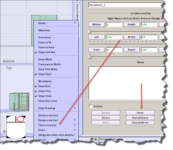
clone form

  • There is a clone button on the object form to the right of the SketchList 3D main screen
  • Right clicking the object opens a menu from which you can select the clone sub-menu. On that sub-menu you can pick any of the three clone techniques.
  • Right clicking a row in the spreadsheet will open a menu from which you can select the type of clone you desire.
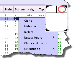
clone sh

Cloning makes an exact copy of the original object. In the general spreadsheet you’ll notice the row is highlighted with the gold background. This means that an object has been cloned but not yet changed. This highlighting helps you see that there are indeed two objects in exactly the same space. When you change the name of the cloned object the gold highlighting will go away.

Usually the next step is to relocate the cloned object.

Clone and mirror makes a copy of the original object but inverts it left to right. If you had a bookshelf on the left of an assembly and drawers on the right cloning and mirroring would result in the second assembly where the drawers would be on the left and the bookshelf would be on the right.

Clone and space makes one or more copies of the original object. Objects may be clone and space in any of three directions – bottom to top, left to right, front to back.
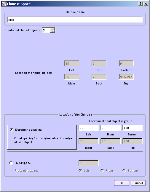
form for clone and space

There are two different ways to do the spacing.

Fixed space between the cloned objects.  The space between, for example, the tops of shelves         and the bottom of the next shelf are equal for all pairs of shelves in the group. This way you can determine that the spacing between two objects would be a fixed amount, for example 10 units.

 Variable space between cloned objects. The space between the objects is calculated over a span you specify. The beginning of the span is the original location of the selected object. You enter the end of the span.   The ending of the span is set to the inside edge of the last object.   For example if a bookcase height is 100 units and the thickness of the shelf is one unit the ending span would be set to 99. The form provides a calculation to show the top, right, back edge of the last copy of the object.

In fact with the variable spacing option you can clone and space the boards in more than one direction. In the example below the boards were cloned and then spaced in all three directions. This provides a bit of a staircase functionality in SketchList 3D.

multi direction clone

Clone and space capability also exists within the round a non-round hole functions of SketchList 3D.  In that case you can select a hole and clone and space it.

Categories
Blog Uncategorized

Cabinet Design – grain, orientation, and materials

Cabinet Design Software – using board definition  tab to change grain, orientation and materials.

Creating a new board in SketchList 3D cabinet design software establishes a definition of that board that contains information about the orientation (what it looks like from the front of the assembly), grain direction, material type (for example sheet or dimension lumber), and material (species or appearance).

There are times when you may want to change some aspect of that definition.

To do that click on the board definition tab on the right side of the SketchList 3D cabinet design software main form.

 board defintion tab

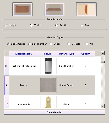
 That opens the board definition form.  The current values for that board are already set in the form. If you want to change any just click an alternative value.

You may change any or all of four elements of the definition.

  1. Orientation – the way the board looks from the front of the assembly. This is really setting the board thickness so one SketchList 3D runs the Optimizer it knows how to lay this board onto the source material.
  2. Grain direction – the direction of the grain. The option any essentially means you don’t care.
  3. Material type – usually sheet goods or solid lumber, but there are other types of material such as glass, leather, or metal to name a few. There are also objects as a material type. In this category you may have stored an image of a refrigerator for example.
  4. Material – this is the name and the visual appearance (grain image) of the material you’re choosing for this board.

board definition form

When you’re finished adjusting that board definition move your cursor off of the new board form and it will close.

Watch the video.

Cabinet Design Software – using board definition tab to change grain, orientation and materials.

Creating a new board in SketchList 3D cabinet design software establishes a definition of that board that contains information about the orientation (what it looks like from the front of the assembly), grain direction, material type (for example sheet or dimension lumber), and material (species or appearance).

There are times when you may want to change some aspect of that definition.

To do that click on the board definition tab on the right side of the SketchList 3D main form.

board definition tab

That opens the board definition form. The current values for that board are already set in the form. If you want to change any just click an alternative value.

You may change any or all of four elements of the definition.

Orientation – the way the board looks from the front of the assembly. This is really setting the board thickness so one SketchList 3D runs the Optimizer it knows how to lay this board onto the source material.
Grain direction – the direction of the grain. The option any essentially means you don’t care.
Material type – usually sheet goods or solid lumber, but there are other types of material such as glass, leather, or metal to name a few. There are also objects as a material type. In this category you may have stored an image of a refrigerator for example.
Material – this is the name and the visual appearance (grain image) of the material you’re choosing for this board.

board definition form

When you’re finished adjusting that board definition move your cursor off of the new board form and it will close.

Watch the video.

Categories
Blog Uncategorized

Cabinet Design Software – doors & drawers.

How to add doors and drawers with you cabinet design software.


Lesson – creating and using containers


To enable you to become more proficient SketchList 3D cabinet design software supports multiple level containers for your designs.  A container is any object that holds or contains other objects.  lockers design 1


The advantage of containers comes from the fact that actions taking with a container are instantly taken on all members of that container. This means you can create groups of objects. These groups may be:


  1. Moved
  2. Deleted
  3. Cloned
  4. Saved as a standard in your library for use in other projects.


hierarchy containers


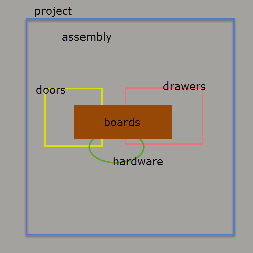
There are four types of containers in SketchList 3D.

  1. Assemblies
  2. Doors
  3. Drawers
  4. Hardware

You can have any number of any of these containers in your project. The exception is you must have one assembly.

The relationship between the containers is as follows.

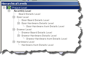
  • Project contains one or more assemblies. You can only insert assemblies into projects. When an assembly is inserted into a project by default it is made the same size as the project.
  • Assemblies may contain doors, drawers, or hardware. Assemblies may also contain boards but technically a board is not a container.
  • Doors may contain hardware and or boards.
  • Drawers may contain hardware and/or boards.
  • Hardware may contain boards – although when speaking of hardware we generally think they contain material.
  • Boards are simply objects. They have different attributes and this will be covered in future lessons.


Any new object in SketchList 3D cabinet design software is inserted at the point of origin of its container. The tasks are to take they object and change its size and location.


In order to insert, locate, size or otherwise modify objects in a container you must be at that level of the container.


You can change the level at which you are working by clicking the level on the Hierarchical levels form, or double left clicking the object on the image area of the screen.

heirarchy outlineinsert new asby


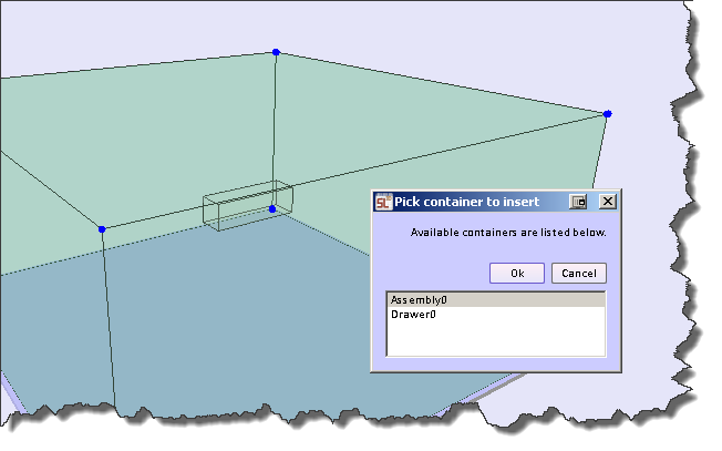
If you start an action, for example insert a board, and SketchList is unclear about which container you intend to receive the board, a form will open. Click the desired container and click OK.


level query


Containers are like any other object in terms of resizing for locating them. If you view the videos on resizing and locating a board and locating boards in relationship to each other you can apply those techniques to containers.


Inserting a new assembly.


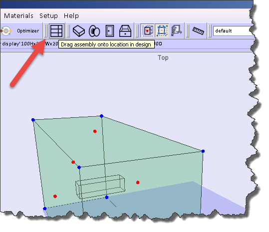
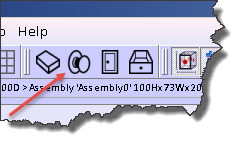
To insert a new assembly click on the new assembly icon near the top of the SketchList main form. An assembly equal to the size of the project will open. Double left clicking the assembly will put you at the assembly level and allow you to begin inserting objects into that new assembly.


insert new asby


Inserting a door or drawer.


Doors and drawers are containers that act as sub-assemblies.


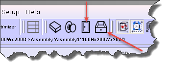
insert new door drawer

Clicking on the door icon or the drawer icon inserts those containers into the assembly. You must be at assembly level.


To create the door or drawer, go to the door or drawer level by double clicking the outline image in the image viewing area. At that point the door or drawer becomes the container for your boards. You drag the new board into one of these containers the steps are exactly the same as they would be for inserting a new board into an assembly.

NOTE:  You can use a door as a substitute for a frame or any other subassembly.


Inserting hardware.


Hardware is also container that can be inserted into one assembly. It is different from doors or drawers in that hardware may be inserted into a door or drawer.

hardware


To create hardware click on the hardware icon near the top of the screen. Drag that icon into the container where you want to place the hardware. When the small hardware cube appears double click it. Now drag a “board” into that hardware. We use the term board but really mean material. When you create the “board” you want to design. There are materials that are similar to brass or bronze and steel in the database.

NOTE


Every object in SketchList 3D is located relative to the point of origin of its container. Sometimes this may confuse you. For example if an assembly is 48 units to the right, and a board in the assembly has a left value of zero, you might think that that board should have a left value of 48. There is a way to clarify this in the software

.

locdate relative


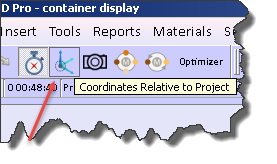
Little icon with three arrows going in the different directions will change the location values from being based on the point of origin of a container to being a based on the point of the origin of the entire project. In the example above then the left value of the board will be 48 – which is the distance that board is away from the left edge of the project. You can easily go from one mode to another as needed.


Watch the video.


Categories
Blog Uncategorized

Built in Storage – Design and Built to Fit

Built in storage saves space and hides junk…

Built in storage, bookcase, and entertainment centers are really in demand.  Either for your personal use, or by the request of a prospect – these units are hot.  They are perfect for SketchList 3D because they tend to be large and complex, offer opportunities to use objects from the library, and tend to be a design and copy type of project.  A while back a survey showed us that nearly 60% of SketchList  3D users had designed at least one built in storage unit with the software.

This is a great example of the type of built in storage I’m talking about.   It rescues a lot of room area from a more or less otherwise hard to use corner of this bedroom.  And yet it fits in perfectly.  Why?

The ability to design on the computer provided the ability to try and try again with different approaches.  The ability to show such great details [angled corners, molding on top. drawer fronts] at the design stage gives you a sense of what you will accomplish.

Beyond the design stage go the reports and drawings necessary to pull the finished work off.

Well heck – let me share the email from this SketchList 3D user with you.

“Just wanted to send you some of the pictures of the built-in that I designed using SketchList 3D.  This was probably the largest most complex project I ever attempted and knew that I needed some drafting help.  I purchased SketchList 3D and began designing.  I don’t think there would have been any way for make all the design changes and construction details without SketchList 3D.  What was really great was the program which optimized and laid out the cutting diagrams for all of the sheets of plywood.  Rather than having to cut the 4 x 8 sheets of plywood in my small shop, I just gave them to my supplier who cut everything to size.  So for a small fee, I was able to save hours of wrangling large sheets of plywood into about 100 different pieces.  Thanks again for a wonderful product.”

What a great concept – asking the lumber yard to cut the sheets.  I am getting too old to ‘wrangle’ 4 x 8 sheets around anymore.

Thanks for the nice feedback Mike!  Question – will the dog let you pass?

If you have a design to share – send in a photo[s] and let me know what you’ve accomplished.

Categories
Blog Uncategorized

Furniture design software video – crown molding

This post and video will show how to make a mitered crown molding trim with SketchList 3D furniture design software.

We received an email this week from a user who is asking how SketchList 3D free furniture design software can be used to create a crown or cold molding. He also wanted to know how to take that molding and turn it around the corner by making a 45° miter cut.

The important thing to know about this is to pick the right orientation of the board when you insert it. The first board facing the front would have the same orientation as a shelf. This is to say the edge of the board would be facing forward the surfaces of the board facing up and down.

If you’ve created your cabinet without enough room on the left side and front side to fit the molding piece, you can use the batch move function at the project level to move all boards in the cabinet to the right by the necessary distance. This is usually the thickness of the molding piece. You can also use that same batch move function to move all of the board to the cabinet back away from the front edge of the assembly, again by the thickness of the molding piece.

Select the board the detail level. This can be done by double left mouse clicking the board. And click the contour button the SketchList form.  Select the contour you want to apply. Look at the contour as cut in the little viewing area of the contour form it may be facing the “wrong way”. If so change the radio button in the contour form from top to bottom or bottom to top.

When you’re done with that go back to the board detail level rotate board in the perspective view such that you can see the top surface. There be a green slice at the back of the board. Click on that with your mouse and click on the shape button. In the shaping tool click on the select button then click on the back left point on the board. The drag that number of units equal to the thickness of the board and you’ll achieve a 45° cut. Repeat the process with the right edge of the board.

Watch the video and you’ll see how I did it.

Categories
Blog Uncategorized Version 4

Cabinet design software — hide and show objects

Cabinet Design Software Needs the Ability to Hide and Show Objects….

SketchList 3D cabinet design software is continually evolving.   As we talk with users, conduct our surveys, and interact during our online training sessions we get lots of suggestions for improvements and new features.

When a suggestion makes sense and we decide to act upon it, our design team determines when and how we can best add it.

Well the latest group of suggestions included the ability to hide and show selected containers – assemblies, doors, and drawers.   This provides you the ability to not only  ‘see behind’ an object, but also work on under lying objects and design elements as if the hidden container did not exist.  You can also for example, hide a door temporarily and do a rendering for a client to show him or her how the shelves are laid out.  Another place where hiding is useful is when you are creating shop drawings.   For example you can hide a door and dimension the shelving behind that door.

The way to hide is straight forward.     Select the container you want to hide.  right click on the image of that container and select ‘hide selected’ from the menu list.Alternatively you can select the container – in the image area or as a spreadsheet row – can click on the  check box in the Hidden column.  To show again — un-check this box.

So if you have any suggestions – trying to improve our 3D cabinet design software – please send them into me.  Many of the features – any many improvement to features – within SketchList 3D came about from user input, suggestions, and yes even criticism.   If there is something you’d like to see in the product, of changed, send us an email.

[aio_button align=”center” animation=”none” color=”red” size=”small” icon=”film” text=”View You Tube Video” relationship=”dofollow” url=”https://youtu.be/yw66wfW6DDA”]

Thank you.


Categories
Blog Contractor Uncategorized Version 4 Version 4 Video Woodworking Business

Cabinet design software inserting shelf pin holes.

V4_hole_space

This is an introduction to holes and hole cloning in SketchList 3D cabinet design software.

This is a very useful feature if you are using shelf pins in your cabinetry. The basic process is to take a board and insert a hole at your first location.

When the hole is set up the way you want exit the form.  Next click on the edit holes button.  When the hole spreadsheet opens right-click on the row containing information about the hole you want to clone.  Pick clone and space from the menu list that opens.

Enter the number of holes you want to insert and the space between the holes.  Select if you want to clone horizontally or vertically.  You will see that SketchList 3D equally spaces those holes on the center line of the holes.   Exit the form.

At this point you might clone the existing holes but sometimes it is just easier to create another new hole for second line of shelf pin holes.

This basically involves repeating the process described above.

When finished do a ‘clone and mirror’ to make a mirror image copy with the shelf pin holes on the inside surface of the board.

Categories
Blog Contractor Uncategorized Version 4 Version 4 Video Woodworking Business

Not Only Cabinet Design Software – Design Almost Anything

Realistic Images in cabinet design software

Not limited to cabinet design software.  How Would You Like a TV, Painting,  or Fireplace..in your design?

Since I published the blog post showing and telling about William LaRue’s  built-in bookcases I’ve gotten several e-mails asking:  “Well how did he do that”?  First answer – he’s real smart.  Second answer – smart enough to buy SketchList 3D.

Well today I put together a video to show you at least in part how he did that.   His proposal to his client was very detail and very complex. The attached video shows how I took an image of a television and imported that image into SketchList 3D as a new material.

Then I took that material and set  its size  to 30 inches wide by 20 inches tall both in the horizontal and vertical scale section of the new material dialogue, and in the material size window.

Inserting a board into an assembly I picked the material called  TV for that board.  Using the flat orientation with the grain direction running top to bottom I size that board to be 20 inches tall and 30 inches deep.

You can see the result of the board in the image the top of this blog post.  The next steps had to do with putting on a black material as sides and back onto the television.

It’s really not that difficult and if you tried a few times you will get it.  When I first started this I had some of the grain directions incorrect and maybe the scaling factors were off a bit.  As I learned and adjusted it became almost trivial to create these objects.
It seems that you can do just about anything that has flat surface.   In fact for the stove that I have in my appliance library I used an image of the front of the stove for the front, and I took an image of a top of the stove with the burners and use that as the top of the stove.   Sandwiched between two base cabinets it looks very realistic.  So I guess like the headline says – SketchList 3D is really more than cabinet building software.  But of course it does that very well also.

When I get a bit more time I’m going to experiment taking some photos of objects with a green background.   My editing software allows me to then drop that green off so the image will stay with no background. I’m thinking of something like a trophy that you might put on the mantle or a mantle clock.

As we start planning for version 5 of SketchList 3D  it may very well be that we can have the ability to import real CAD files and create real 3-D objects in your cabinet design software.  The development jury is still debating that one.

Send me an e-mail and let me know how it goes.   Anyone else up for pasting a blog / story about SketchList 3D?


Categories
Blog Contractor Uncategorized Version 4 Woodworking Business

Cabinet Design Software Enables Face Frame Placement

Face Frame on Case

How to place face frames on your case work.

Had an good online training session Saturday morning with a few SketchList 3D users.  Covered placing objects and moved onto joinery – dado placement on board surfaces.   One user wrote in that it helped him along and still had a question on face frames.

So here is a video on using the cabinet making software for putting frames onto your case work.  It is basically a matter of placing – in this case – five boards on the front.  Remember the ‘back’ value of the frame must equal the ‘front’ value of the case boards!  In addition you use the FLAT orientation for frames – since you are looking at the assembly from the front and want to see the rail or stile surface and not its edge.  Grain direction – usually – is width for rails and height for stiles.  Match up the various lefts and rights, tops and bottom and you will be all set.

What I forgot!  Of course you can contour the corners of the frames and / or miter them as well.  They are just like any other board in SketchList 3D.